Making diagnostic connections, Temporarily connecting to uniconfig, Reconfigured. see – Grass Valley NV5128 v.2.5 User Manual
Page 72: Installation
62
Rev 2.5 • 24 Sep 09
3. Installation
Making Diagnostic Connections
How to make GSC Node Bus connection to the router control system
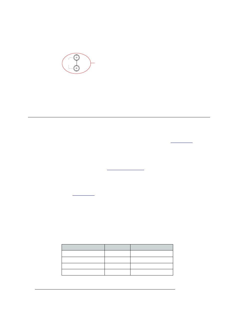
1 Locate the GSC Node Bus connection on the rear of the router, as shown in Figure 3-15. The
GSC Node Bus connection is labeled ‘NODE BUS’.
Figure 3-15. GSC Node Bus Connection to Control System (Rear View)
2 Connect to the ‘NODE BUS’ connection using a 75
ohm BNC connector and coaxial cable.
3 Connect the other end of the coaxial cable to the router control system.
4 Important: Install a 75
Ω BNC terminator on any unused GSC Node Bus loop-through connec-
tions.
Making Diagnostic Connections
The diagnostic connections enable the NV5128 to communicate with the UniConfig application.
UniConfig is installed on hardware (e.g., a PC), separate from the router, and is used to perform
system setup tasks, and configure and monitor the router. (See Chapter 4,
page 67.) For information about using UniConfig, see the UniConfig User’s Guide.
There are two types of diagnostic connections: temporary and permanent. A temporary diagnostic
serial connection is located on the front of each control card. Permanent diagnostic serial connec-
tions are located on the rear of the router, labeled ‘DIAG’. For a detailed description of the perma-
nent diagnostic connections, see
Temporarily Connecting to UniConfig
A temporary connection is created through the DE9 port located on the front of the primary control
card. (See
on page 21.) This connection is set to RS-232, DTE, 9600 baud, 8 data
bits, no parity.
How to make a temporary diagnostic connection
1 Locate the primary control card slot, as shown in Figure 3-8 on page 51. When facing the front
of the router, the control cards are located in the upper, right-hand section.
2 On the front of the control card, connect to the DE9 connection using a DE9 connector and a
serial cable set for EIA-232.
The following lists the wiring for the DE9 pin connectors for RS-232:
LOOP
THRU
GSC Node Bus
Connection
to Control System
NODE
BUS
Hardware
Pins
Router
DCD
1 ------------1
Ground
RXD
2 ------------2
TXD
TXD
3 ------------3
RXD
DTR
4 ------------4
DSR