Diagnostic connections, Aes reference connections, Diagnostic connections aes reference connections – Grass Valley NV5128 v.2.5 User Manual
Page 28: Figure 2-10, next, Introduction
18
Rev 2.5 • 24 Sep 09
2. Introduction
Module Slots and Rear Connectors
Figure 2-10. GSC Node Bus Connections to Router Control System (Rear View)
Control System Expansion Connections
The NV5128 has two connections for the router control system when connecting multiple router
frames together, labeled ‘10 B 2’, as shown in Figure 2-11. However, frame expansion is not sup-
ported in the NV5128 and these connections are inactive.
Figure 2-11. Control System Expansion Connection (Rear View)
Diagnostic Connections
The diagnostic connections enable the NV5128 to communicate with the UniConfig application.
UniConfig runs on external hardware (e.g., PC) separate from the router and is used to perform sys-
tem setup tasks, and configure and monitor the router. (See
on page 67.) For more
information on UniConfig, see the UniConfig User’s Guide.
There are two types of diagnostic connections: temporary and permanent. A temporary diagnostic
serial connection is located on the front of each control card. (See
on page 21.) Per-
manent diagnostic connections are located on the rear of the router, labeled ‘DIAG’, as shown in
Figure 2-12 on page 18. Miranda recommends using the temporary diagnostic connection when
reconfiguring the router because the port has fixed communications parameters. The permanent
diagnostic connections are used for upgrading firmware or control card protocols when there is no
Ethernet connection to the router. For instructions on making temporary or permanent diagnostic
connections, see
Permanently Connecting to UniConfig
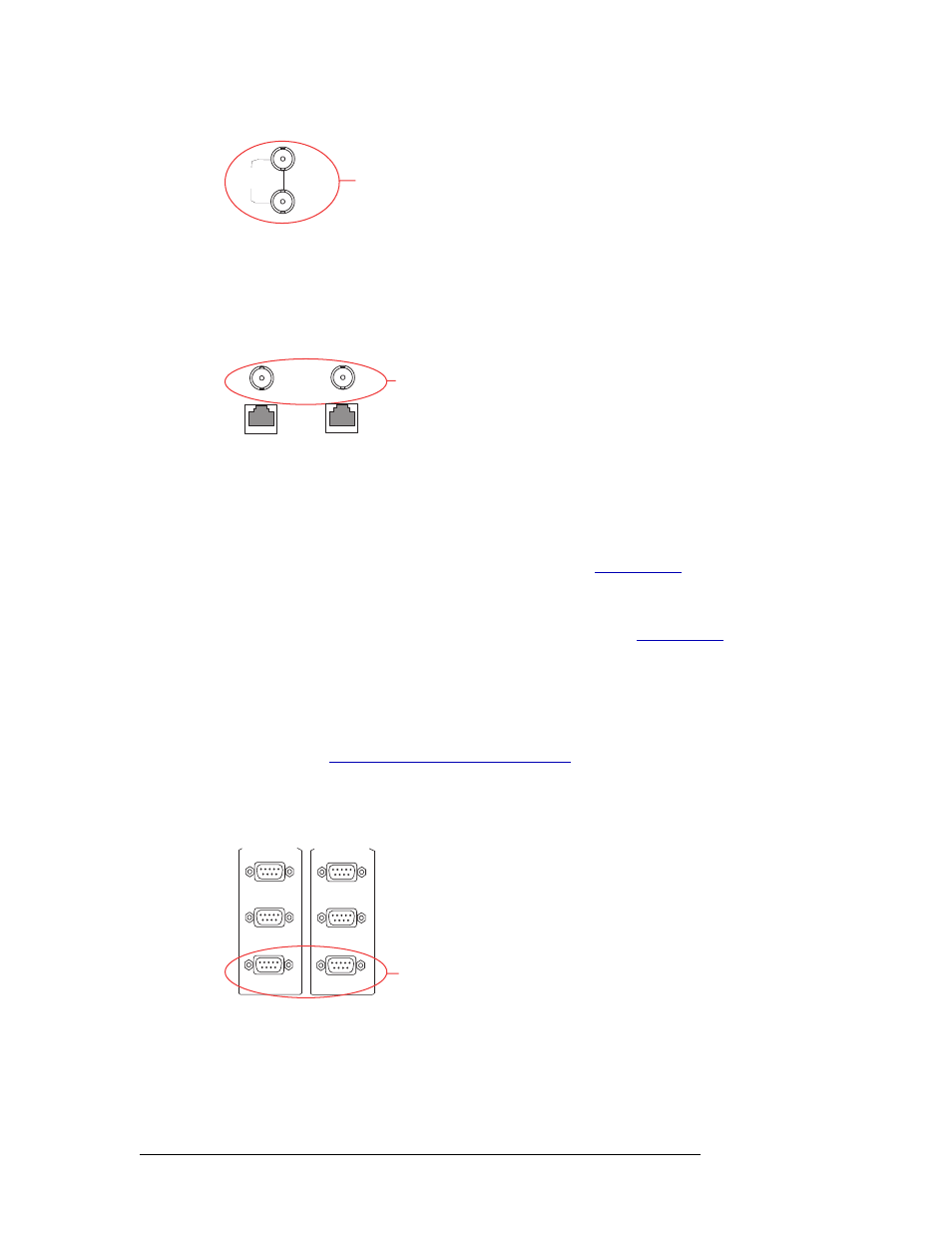
There are two permanent ‘DIAG’ ports, one primary (‘PRI CTRL’) and one secondary (‘SEC
CTRL’). The primary control connects to the primary control card. The secondary control connects
to the secondary (optional for redundancy) control card.
Figure 2-12. Permanent Diagnostic Connections (Rear View)
AES Reference Connections
The AES reference is used for clock generation, which provides a timing reference for AES syn-
chronous signals and for timing circuits on the control card. Certain signals require an AES refer-
LOOP
THRU
GSC Node Bus
Connection
to Control System
NODE
BUS
10 B 2
10/100 B T
10 B 2
10/100 B T
Control System
Expansion
Connection
CTRL 1
CTRL 2
PRI CTRL
DIAG
Diagnostic
Connections
CTRL 1
CTRL 2
SEC CTRL
DIAG