Analog video conversion (avc) card switches, Configuration – Grass Valley NV5128 v.2.5 User Manual
Page 81
NV5128 Multi-Format Router • User’s Guide
71
4. Configuration
Setting Jumpers and Switches on Cards and Card Sets
The DIP is SW4 on the input card and S1 on the output card. Only the first two switches on the DIP
are used for the operating level. The following shows the switch positions for each operating level:
By default, all switches are set to ‘OFF’ and the operating level set to +24
dBu
.
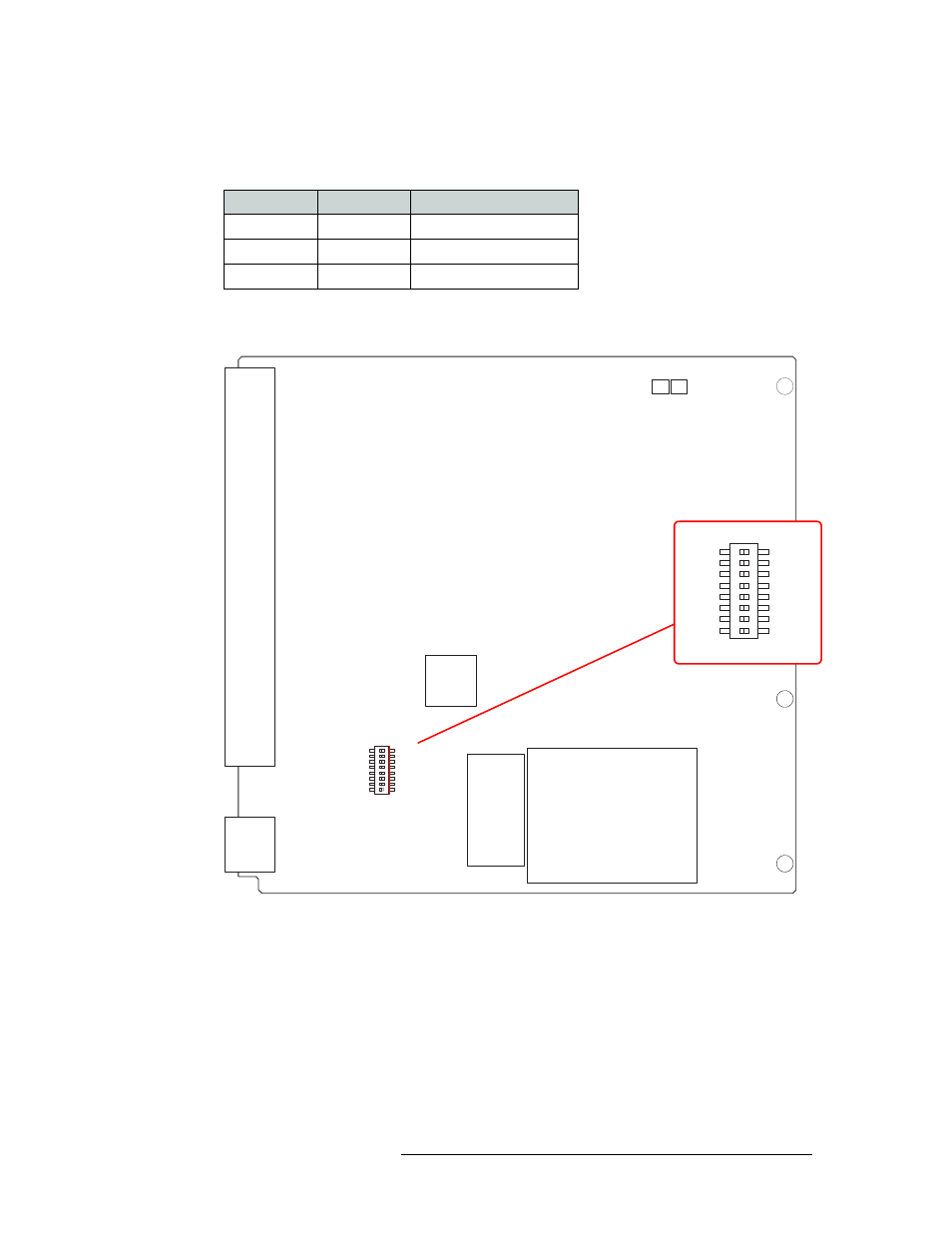
Figure 4-2 shows the location of the DIP switches for analog audio output card (EM0586):
Figure 4-2. Analog Audio Output Card Switch Locations
Analog Video Conversion (AVC) Card Switches
The AVC input card (EM0432) receives incoming composite analog video (NTSC or PAL) and
converts the signal to SD format for delivery to the motherboard. The AVC output card (EM0433),
receives SD formatted signals from the motherboard and converts them to composite analog video
outputs in NTSC or PAL formats. Because the color space for SD signals differs from that of com-
posite signals, the absence or presence of pedestal in NTSC signals must be accommodated if color
and luminance information is to be maintained. To accommodate these differences, DIP switches
Switch 1
Switch 2
Operating Level (Max)
Off
—
+24 dBu
On
Off
+18 dBu
On
On
+15 dBu
DIAGNOSTIC
1
2
3
4
5
6
7
8
OFF
ON
S1
EM0586-
NV5128 ANALOG AUDIO 16 STEREO OUTPUT
NVISION
PC0640-00
DIAGNOSTIC
1
2
3
4
5
6
7
8
OFF
ON
Operating Level