Status reporting, Aes synchronous, Status reporting aes synchronous – Grass Valley NV5128 v.2.5 User Manual
Page 33: Introduction
NV5128 Multi-Format Router • User’s Guide
23
2. Introduction
Active Cards
Status Reporting
All audio input cards and output cards feature a circuit that performs status reporting and drives the
card’s functions. Two LEDs on the front of the card indicate the card’s status: alarm (Red), power
good (Green). Unique to the analog input card, three additional LEDs situated further back on the
card indicate if software is loaded (Amber), and if there is good communication with the control
card (Green) or bad communication with the control card (Red). For more information, see
The functions of each type of card are described in the proceeding sections. Cards are listed by the
signal type supported.
AES Synchronous
Incoming and outgoing AES synchronous signals, balanced or unbalanced, are received or distrib-
uted through passive connectors housed on backplanes: 16 BNC connectors for unbalanced signals
or 16 Phoenix connectors for balanced signals. (See
Input Card
The AES synchronous input (EM0389) receives up to 16 stereo signals through passive backplane
I/O connectors. Each signal is routed as an AES signal and is transformer coupled and forwarded to
a receiver. At that time, the signal is synchronized to the system clock; adding and dropping sam-
ples as needed until the signal is synchronized.
The receiver forwards the signal to a buffer, which in turns sends the signal to the motherboard and
onward to output cards for switching.
Output Card
The AES synchronous output card (EM0390) receives up to 128 stereo inputs from the mother-
board. The signals are sent to receivers and then to a crosspoint array (128 inputs x 16 outputs ste-
reo; 256 inputs x 32 outputs mono) for switching. The crosspoint splits the AES signal into a right
channel, a left channel, and channel status bits for switching as mono signals. Each mono channel
is then recombined with another mono channel to create a new AES signal. The outgoing AES sig-
nals are switched synchronously and sent to drivers and backplane I/O connectors for distribution.
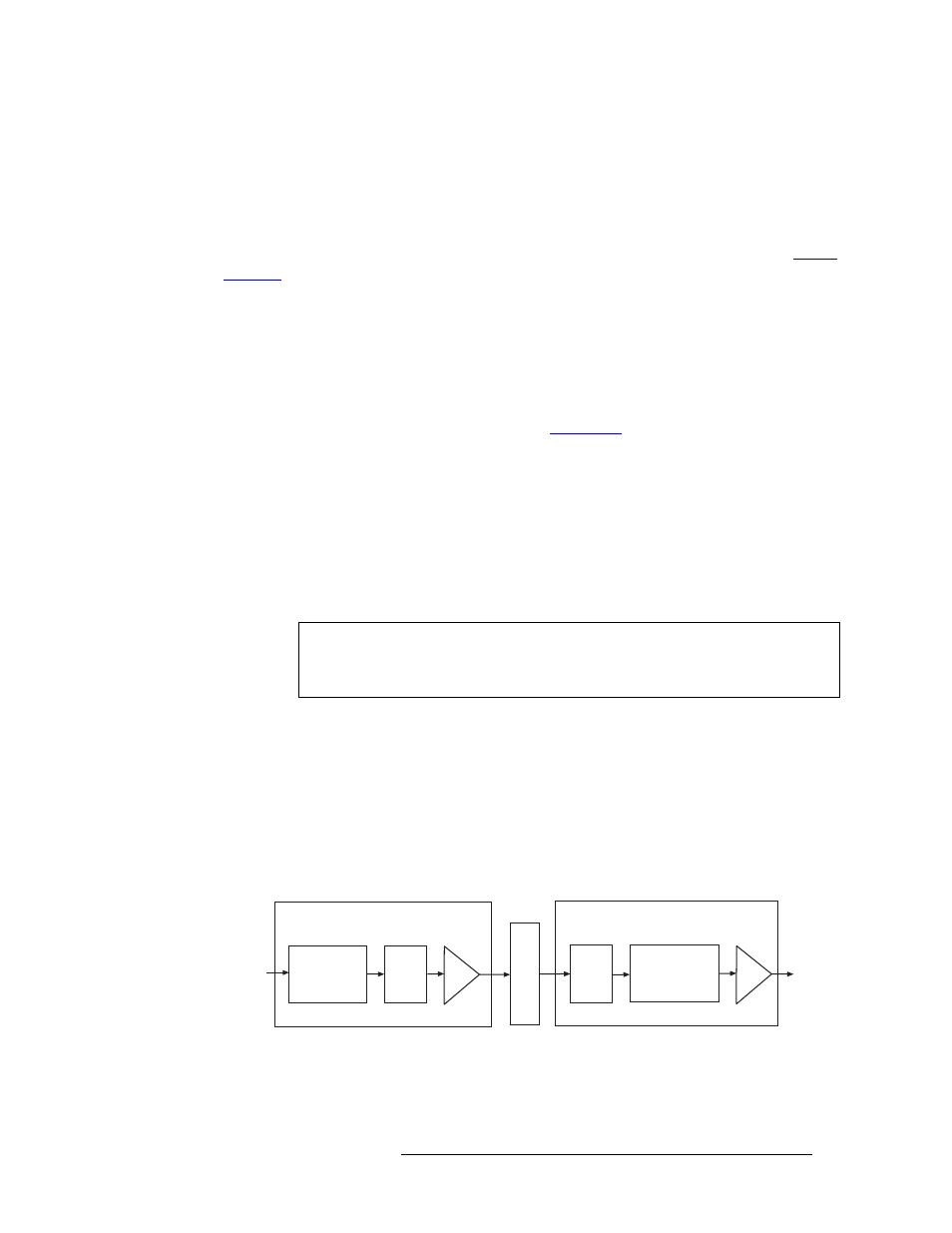
Figure 2-17 shows the synchronous AES signal path.
Figure 2-17. Synchronous AES Signal Flow (Balanced or Unbalanced)
Note
Near-synchronous operation may cause minor disturbances in the audio signal.
These effects are usually masked by the program audio, depending on the sample
rate offset or magnitude and timing of the disturbance.
I/O
Connectors (up to 16)
Recr
Motherboard
Input Card
Transformer
Coupled
Recr
Output Card
XPT
128x16 stereo
256x32 mono
I/O
Connectors (up to 16)