Installing machine control backplanes, Installing machine control, Backplanes – Grass Valley NV5128 v.2.5 User Manual
Page 52: Installation
42
Rev 2.5 • 24 Sep 09
3. Installation
Installing Backplanes
7 Remove any blank plate covering the desired slot by loosening the spring-loaded retention
screws using a #1 Phillips screwdriver. Gripping the screws, gently pull the blank plate free
from the frame, using a slight rocking motion if needed. Use caution to avoid damaging con-
nector pins.
Or
If reconfiguring the router, relocate backplanes as needed.
8 Insert the new backplane into the frame being sure to align the printed circuit board with the
stamped guides in the frame. Use gentle pressure at the top of the backplane to ensure the back-
plane connector is fully mated with the motherboard.
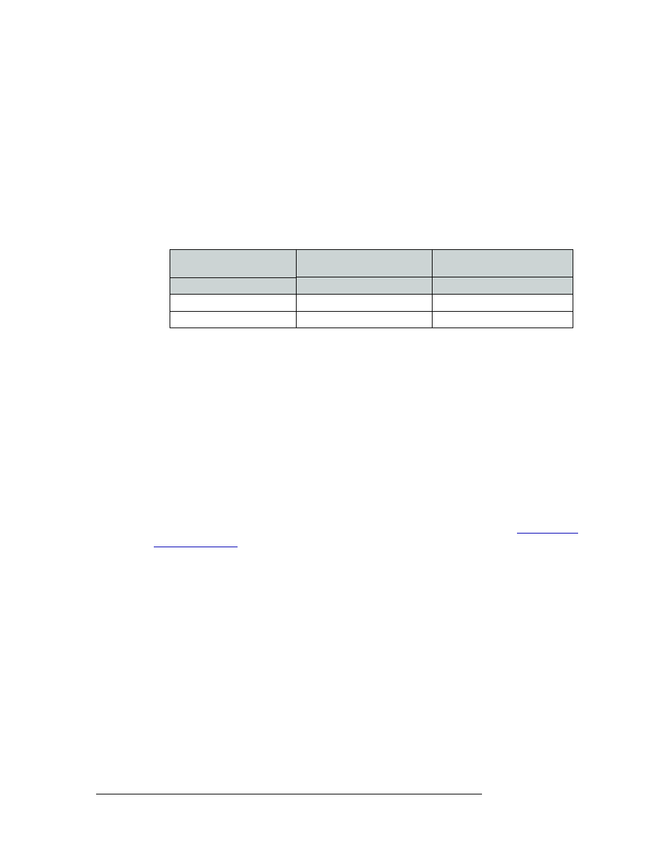
Classic SWB backplanes must be installed in specific slots, as follows:
9 Use a #1 Phillips screwdriver to tighten the two spring-loaded backplane retention screws.
10 To maintain proper airflow for cooling, cover any unused backplane slots with a blank plate.
Installing Machine Control Backplanes
The Machine Control card set requires two backplanes. If you are installing a single Machine Con-
trol card set, the two backplanes may be located in any two adjacent slots associated with the
Machine Control card set. If you are installing two Machine Control card sets (64-port configura-
tion), the two backplanes must be installed in specific slots.
Miranda offers an optional connector breakout panel that can be used to convert up to 64 RJ-45
connectors on the router backplane to 9-pin subminiature D connectors (DE9). This breakout panel
occupies 4RUs and hinges open for easy access and to facilitate cable routing. The DE9 connector
wiring follows SMPTE-defined pin assignment standards. For more information, see
How to install a Machine Control backplane
1 Facing the rear of the router, remove any blank plate covering the desired slot by loosening the
spring-loaded module retention screws using a #1 Phillips screwdriver. Gripping the screws,
gently pull the blank plate free from the frame, using a slight rocking motion if needed. Use
caution to avoid damaging connector pins.
Or
If reconfiguring the router, relocate backplanes as needed.
2 Insert the new backplane into the frame being sure to align the printed circuit board with the
stamped guides in the frame. Use gentle pressure at the top of the backplane to ensure the back-
plane connector is fully mated with the motherboard.
Number of Classic SWB Card
Sets installed
Slot Number
Slot Number
Part Number:
EM0396
EM0424
One (16 x 16)
Install in slot 12
Install in slot 13
Two (32 x 32)
Install in slots 11 and 13
Install in slots 12 and 14