To see a complete list of possible operating con – Grass Valley KAM-XM-SERIES v.1.4.1 User Manual
Page 20
20
KAM-XM-SERIES Instruction Manual
Power Up and Module Status
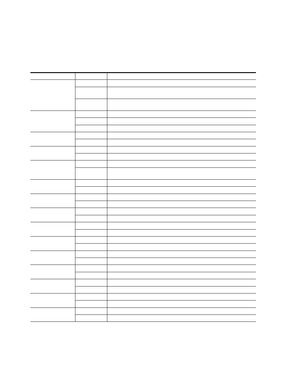
A red FAULT LED indicates an error situation and, when noted with the
other indicator LEDs, can indicate a specific problem area.
describes
signal output and LED indications for the various input combinations and
user settings.
Table 4. Indicator LEDs and Conditions Indicated
LED
Indication
Condition
FAULT
(red)
Off
Normal operation.
On continuously
Module has detected an Optic 1 or Optic 2 internal fault from the submodule or a write failure has
occurred on the front module.
Long flash
No input is detected for the input or the input does not match the format selected manually, no rear
module is present, or the wrong rear module is present.
COMM
(yellow)
Off
No activity on frame communication bus.
3 Short Flashes
Location Command received by the module from a remote control system.
Short flash
Activity present on the frame communication bus.
CONF
(yellow)
On
Module is initializing, changing operating modes, or updating firmware.
Off
Module is in normal operating mode.
PWR +3.3
(green)
Off
No power to module, fuse blown, or module’s DC/DC converter failed.
On continuously
Normal operation, module is powered.
SEQ ACT
(green)
Off
Input video not detected or PLL unlocked.
Blinking
Normal operation, Sequencer Active LED should be blinking to Indicate good video input and PLLs
locked.
TC PRSNT
(green)
Off
No timecode or bad timecode.
On
Good timecode is detected.
AUD PRSNT
(green)
Off
No embedded audio detected.
On
Embedded audio detected.
FRM LOCK
(green)
Off
Input to output frame rates are not locked.
On
Normal operation, input to output frame rates are locked.
FBREF ERR
(yellow)
Off
No FrameBuilder refresh error detected.
On
FrameBuffer refresh error detected, output could be corrupted such as bad output image.
UCREF ERR
(yellow)
Off
No Microcode refresh error detected.
On
Microcode refresh error detected, Microcode memory could be corrupted.
OFF ERR
(yellow)
Off
Normal operation, no Output FIFO underflow/overflow error detected.
On
Output FIFO underflow/overflow error condition detected.
IFF ERR
(yellow)
Off
Normal operation, no input FIFO underflow/overflow error condition detected.
On
Input FIFO is detecting underflow/overflow error condition.
VOLT TRIP
(yellow)
Off
Normal state, no under voltage trip detected.
On
Under voltage trip detected, one or more supply voltages is below specification.
CH1 STAT
(green)
Off
No input detected or bad input.
On
Normal operation, good input detected.
RESET
(red)
Off
Normal operation, board is not in Reset mode.
On
Module is in reset mode, including FPGA configuration sequence.