Grass Valley KAM-XM-SERIES v.1.4.1 User Manual
Page 14
14
KAM-XM-SERIES Instruction Manual
Installation
2.
Insert the rear module into the vacant rear slot of the frame as
illustrated in
3.
Verify that the module connector seats properly against the midplane.
4.
Using a crossblade screwdriver, tighten
the two screw locks to secure
the module in the frame.
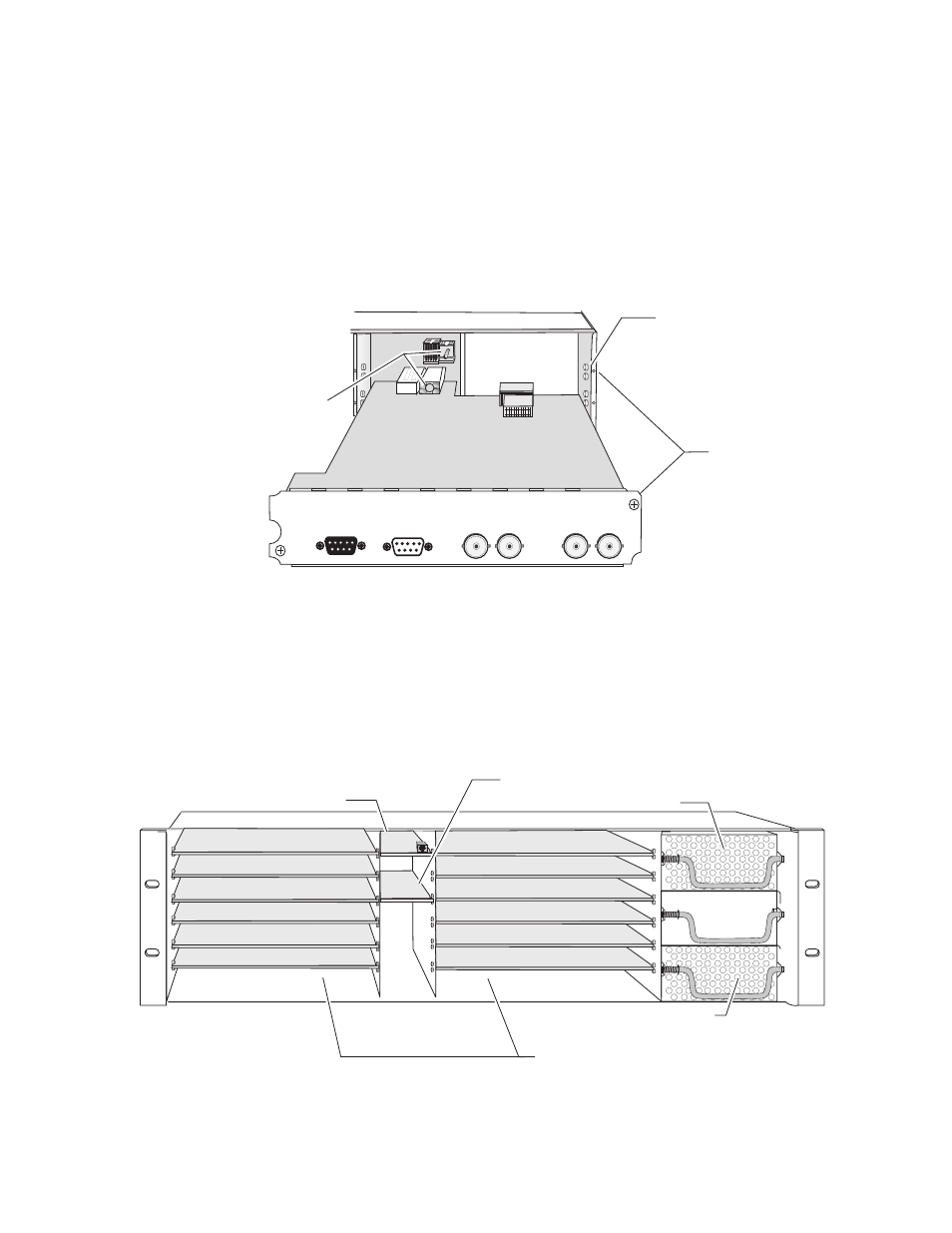
Figure 3. Installing KAM-XM Rear Module
5.
Locate the front slot 2, 4, 6, 8, 10, or 12 in the frame corresponding to the
rear module circuit board. The 3 RU frame front view is illustrated in
and the 1 RU frame is shown in
.
Note
Module slots where the KAM-XM should be installed are highlighted in gray
for a fully stuffed 2000T3 frame and for any 2000T1 frame.
Figure 4. 2000T3 Frame, Front Slots
Alignment post
and receptacle
Screw locks
(both sides)
8
330_03r1
2000 frame (rear view)
Board edge guides
(both sides)
J1
LOOP
IN
OUT2
OUT1
RS-232
GP10
J2
J4
J5
J5
J7
(2)
(3)
(4)
(5)
(6)
(7)
(8)
(9)
(10)
(11)
(12)
(15)
(13)
(1)
8
173-04r1
Network Slot (13)
Reference Distribution Slot (15)
Main Power Supply Slot (18)
Secondary Power
Supply Slot (20)
Front Media Slots (1-12)
Fan Sled
Slot (19)