Cabling, Kam-xm-r rear module connections, Ear module signal connections – Grass Valley KAM-XM-SERIES v.1.4.1 User Manual
Page 16
16
KAM-XM-SERIES Instruction Manual
Installation
Cabling
All cabling to the KAM-XM module set is done on the corresponding Dual
Height KAM-XM-R rear module (XM-IO-1) at the back of the 2000 frame.
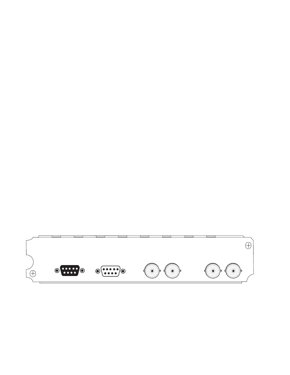
KAM-XM-R Rear Module Connections
for an illustration of the KAM-XM rear module.
The KAM-XM rear module provides the following input and output and
control connections.
•
IN (BNC)– a serial digital input that may be either standard definition
(SD) or high definition (HD) video depending on the front module
type.
•
LOOP (BNC)– provides an output for the input signal to be looped to
another destination.
•
OUT1 (BNC)– this serial digital output connection can be either SD or
HD depending on the front module type and the output format
selected.
•
OUT2 (BNC)– this serial digital output connection can be either SD or
HD depending on the front module type and the output format
selected.
•
RS-232 Port (DB-9, Male) – this serial port allows a direct interface to the
module for testing and configuration purposes. This port is not nor-
mally used.
•
GPI0 Port (DB-9, Female) – this port allows connection of external GPI
(General Purpose Interface) signals to the module as described in
Connections for GPI Control on page 18
.
Figure 7. KAM-XM Rear Module Input/Output Connectors
J1
LOOP
IN
OUT2
OUT1
RS-232
XM-IO-1
GPI0
J2
J4
J5
J6
J7
8330_02