Common proxy arp configuration example, Network requirements, Configuration procedure – H3C Technologies H3C S12500 Series Switches User Manual
Page 27
14
Task Command
Display common proxy ARP status. display proxy-arp [ interface interface-type interface-number ]
Display local proxy ARP status.
display local-proxy-arp [ interface interface-type interface-number ]
37B
Common proxy ARP configuration example
NOTE:
By default, Ethernet, VLAN, and aggregate interfaces are down. To configure such an interface, bring the
interface up by executing the undo shutdown command.
173B
Network requirements
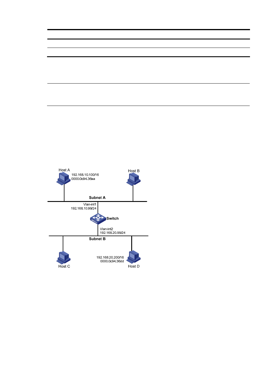
As shown in
661H
Figure 5
, Host A and Host D have the same IP prefix and mask, but they are located on
different subnets separated by the switch (Host A belongs to VLAN 1, and Host D belongs to VLAN 2).
No default gateway is configured on Host A and Host D.
Configure common proxy ARP on the switch to enable communication between the two hosts.
Figure 5 Network diagram
174B
Configuration procedure
# Create VLAN 2.
[Switch] vlan 2
[Switch-vlan2] quit
# Configure the IP address of VLAN-interface 1.
[Switch] interface vlan-interface 1
[Switch-Vlan-interface1] ip address 192.168.10.99 255.255.255.0
- H3C SR8800 H3C SR6600-X H3C SR6600 H3C WX6000 Series Access Controllers H3C WX5000 Series Access Controllers H3C WX3000 Series Unified Switches H3C LSWM1WCM10 Access Controller Module H3C LSWM1WCM20 Access Controller Module H3C LSQM1WCMB0 Access Controller Module H3C LSRM1WCM2A1 Access Controller Module H3C LSBM1WCM2A0 Access Controller Module H3C S6800 Series Switches H3C S3100V2 Series Switches H3C S12500-X Series Switches H3C S9800 Series Switches