3 jumpers and dip switch – Eneo EKR-32/8 User Manual
Page 80
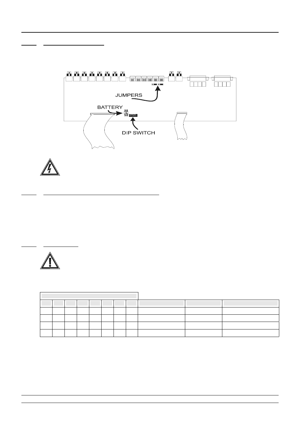
2.3 Jumpers and DIP switch
2.3.1
Opening the matrix
Inside the matrix there are two jumpers (JP1 and JP2, behind the Aux connectors) for inserting the RS485
load, one DIP switch (SW1, near the backup battery in the centre of the board) and a backup battery:
Warning! The operations described below are carried out with the matrix cover removed. Take
great care to prevent the risk of electric shock.
2.3.2
RS485 load
Jumpers on the Aux lines
To comply with the standard, the RS485 communication lines must be terminated at the ends to prevent
signal reflection.
On the Aux A and Aux B auxiliary communication lines the load can be inserted (jumper in the LOAD
position) or excluded (jumper in the NOLOAD position).
JPA is the jumper on the Aux A line, JPB is the jumper on the Aux B line.
2.3.3
DIP switch
To prevent faulty operation of the system, do not make DIP switch settings that are not included
in the following tables.
2.3.3.1
Protocol and baud rate
DIP switch
1
2
3
4
5
6
7
8
Protocol
Baud rate
Notes
off
off
off
off
-
-
-
-
Macro
38400
default
ON
off
off
off
-
-
-
-
Macro
19200
off
ON
off
off
-
-
-
-
Macro
9600
ON
ON
off
off
-
-
-
-
Macro
1200
•
2. System installation
Page 12/65
MNNCEKR328_0439