Service table screen, Service table screen -17 – Verilink WANsuite 7205 (34-00317.B) Product Manual User Manual
Page 139
V T 1 0 0 I n t e r f a c e
4-17
Stop Bit
Selects the number of bits required to end the character.
Values: 1, 2
Default: 1
DTR Alarm Control
Choices for DTR Alarm Control are “Enable” and “Disable”; the default
setting is “Disable.” Setting DTR Alarm Control to “Enable” allows the unit
generate an alarm upon loss of DTR, which occurs when the Serial port
detects that the DTR signal is low.
Values: Enable, Disable
Default: Disable
DTR Alarm Status
Lets you view the current DTR Alarm status.
Diagnostic Messages
Enables the Supervisory port to send out diagnostic messages upon power-up.
Values: Enable, Disable
Default: Enable
NOTICE:
When in SCADA mode, these diagnostic messages disrupt the connected
device. Therefore, if using the SCADA mode, set this value to
“Disable.”
Current Pin Status
Shows the status of the DTE Supervisory port pins.
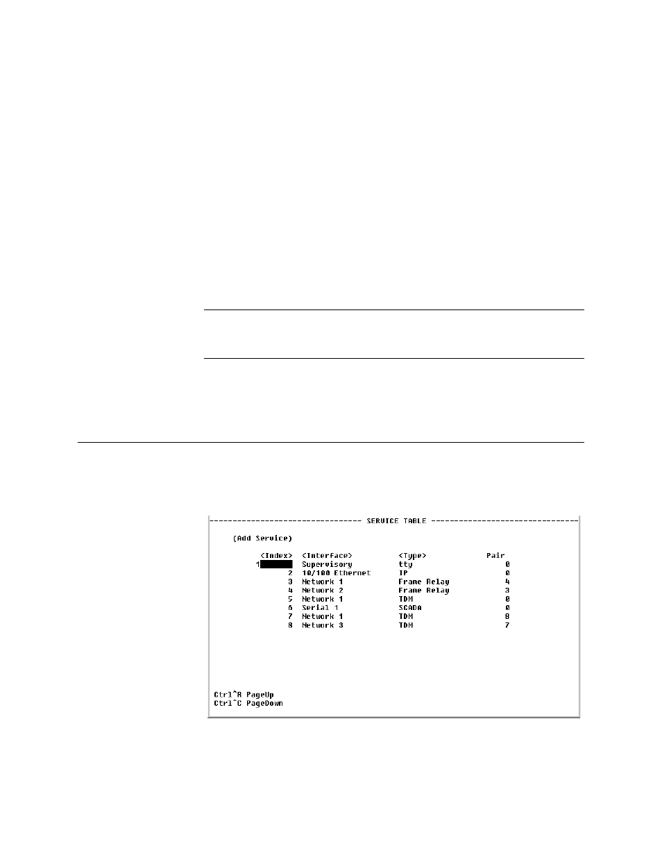
Service Table Screen
The Service Table screen (Figure 4.13) provides a view of the unit’s defined
services and displays the Interface, Type, and Pair parameters for each
service.
Figure 4.13
Service Table Screen
The Service Table screen displays the available services listed by Index
number. From the Service Table screen, you can navigate to a Service Details