Sundance SMT950 User Manual
Page 13
Version 2.0
Page 13 of 52
SMT950 User Manual
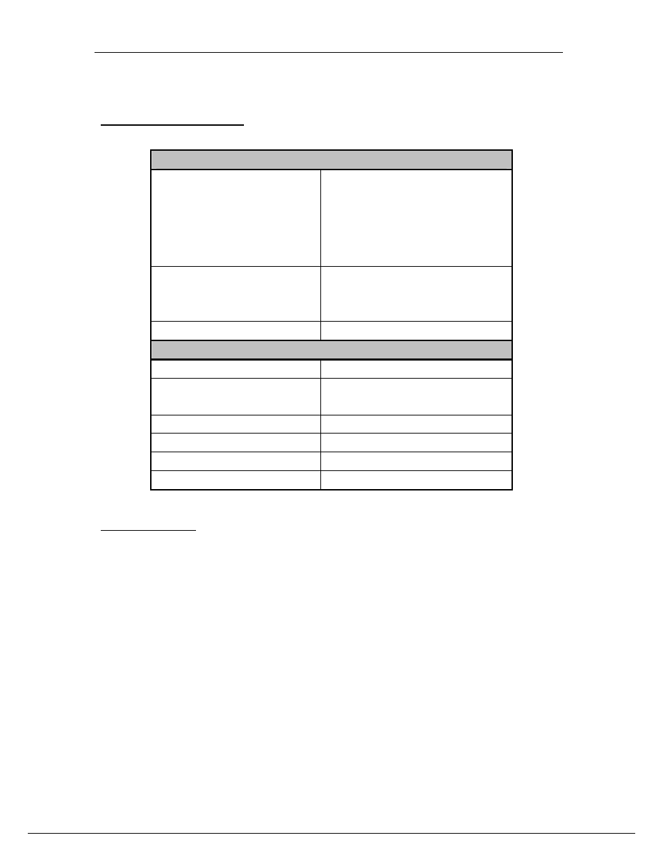
ADC Channels.
ADC Main Characteristics.
The main characteristics of the SMT950 ADCs are gathered into the following table.
Analogue Inputs
Input voltage range
AC coupled option. 2.4 Vp-p (11.5 dbm –
50 Ohm) Full scale - AC coupled.
DC coupled option. 1.15 Vp-p (Gain
amplifier 6dB) centered around 0. DC
coupled via amplifier. Gain can be adjusted
to a required input amplitude centered
around 0. Minimm gain 6dBs, which should
allow input swing +/-0.575V as full scale.
Impedance
ADC single-ended inputs are to be
connected to a 50
Ω source. Source
impedance matching implemented between
RF transformers and ADC.
Bandwidth
ADC bandwidth: 750 MHz.
ADCs Output
Output Data Width
14-Bits
Data Format
2’s Compliment or offset binary
(Changeable via control register)
SFDR
82dBs maximum (manufacturer)
SNR
70dBs maximum (manufacturer)
Minimum Sampling Clock
10 MHz (ADC DLL off)
Maximum Sampling Frequency
125 MHz (ADC DLL on)
Figure 3 - Main features.
ADC Input Stage.
Each ADC Analogue input is AC-coupled via and RF transformer (AC-coupled
version of the SMT950). The 50-Ohm resistor between the connector and the first RF
transformer is not fitted because the source impedance match is implemented
between the second RF transformer and the ADC by the way of two 25-Ohm
resistors.