Sundance SMT942 User Manual
Page 11
User Manual SMT942
Page 11 of 55
Last Edited: 23/08/2011 17:25:00
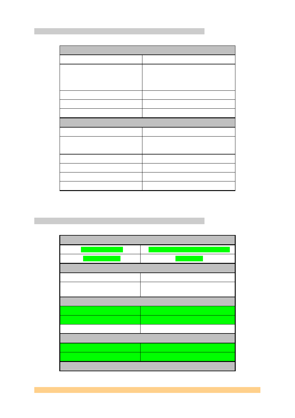
3.2.1 D/A converters
The main characteristics of the SMT942 are gathered into the following table.
Analogue Outputs
Output voltage range
1 Vp-p – Full scale - AC coupled
Impedance
DAC single-ended outputs are to be
connected to a 50
load, which impedance
matching implemented between DAC and
RF transformers.
SFDR
89dBs maximum (manufacturer)
SNR
80dBs maximum (manufacturer)
Bandwidth
TBD
DAC Input
Output Data Width per channel
16-Bits
Data Format
2’s Compliment or offset binary
(Changeable via control register)
SFDR
85dBs maximum (manufacturer)
SNR
73dBs maximum (manufacturer)
Maximum input data rate
250 MSPS (Clk1 – DAC5687)
Maximum Sampling rate
500 MSPS (Clk2 – DAC5687)
Jumper J1 disables (position 1-2; also called External Clock Mode) or enables
(position2-3; also called Internal Clock Mode) the DAC internal PLL.
3.2.2 Clock structure
External Reference Input
Input Voltage Level
1 – 3.3 Volts peak-to-peak (AC-coupled)
Frequency Range
0 – 100 MHz.
External Reference Output
Output Voltage Level
1.6 Volts peak-to-peak (AC-coupled)
Output Impedance
50-Ohm (Termination implemented at the
connector)
External Sampling Clock Input
Input Voltage Level
1.5 – 3.3 Volts peak-to-peak (AC-coupled)
Input Format
Single-ended.
Frequency range
10-500 MHz
External Sampling Clock Output
Output Voltage Level
0-2.4 Volts fixed amplitude
Output Format
LVTTL
External Trigger Inputs