Dds register 2 – stop phase increment lsb - 0x22, Dds register 3 – stop increment msb - 0x23, Mhz) / 2 – Sundance SMT350 User Manual
Page 38
Version 1.9
Page 38 of 45
SMT350 User Manual
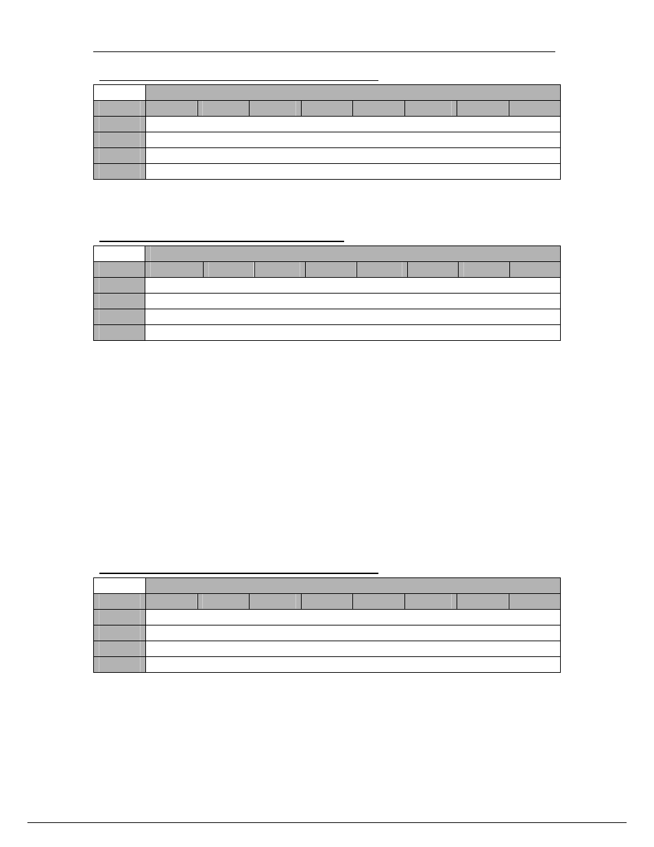
DDS Register 2 – Stop Phase Increment LSB - 0x22
DDS Register 2 – 0x22
Byte
Bit 7
Bit 6
Bit 5
Bit 4
Bit 3
Bit 2
Bit 1
Bit 0
1
DDS Stop Phase Increment [15…8]
Default
‘00000000’
0
DDS Stop Phase Increment [7…0]
Default
‘00000000’
DDS Register 3 – Stop Increment MSB - 0x23
DDS Register 3 – 0x23
Byte
Bit 7
Bit 6
Bit 5
Bit 4
Bit 3
Bit 2
Bit 1
Bit 0
1
DDS Stop Phase Increment [31…24]
Default
‘00000000’
0
DDS Stop Phase Increment [23…16]
Default
‘00000000’
The Stop Phase Increment value is coded on 32 bits (DDS Data registers 0x22 and
0x23). Each value corresponds to a frequency generated worked out as follows :
Fout = Stop Phase Increment * F
DAC sampling
(MHz) / 2
32
When the DDS is used in sweep mode, Start Phase Increment should be lower than
Stop Phase Increment
and Step Phase Increment should be greater than 0. When
used to generate a fixed frequency, Start Phase Increment should be equal to Stop
Phase Increment
and Step Phase Increment should be equal to 1.
For Registers 0x22 and 0x23 to take effect, Bit 5 of register 0x1D must be set to 1.
DAC Channel A is the Sine output of the DDS and DAC Channel B is the Cosine
output of the DDS. Both outputs are therefore is quadrature.
The Maximum Phase increment value supported by the design is 0x40000000, which
corresponds to a frequency of 30.72MHz when sampling at 122.88MHz with no
interpolation.
DDS Register 0 – Step Phase Increment LSB - 0x24
DDS Register 4 – 0x24
Byte
Bit 7
Bit 6
Bit 5
Bit 4
Bit 3
Bit 2
Bit 1
Bit 0
1
DDS Step Phase Increment [15…8]
Default
‘00000000’
0
DDS Step Phase Increment [7…0]
Default
‘00000000’