Maintenance – REMKO GPM 15 User Manual
Page 31
31
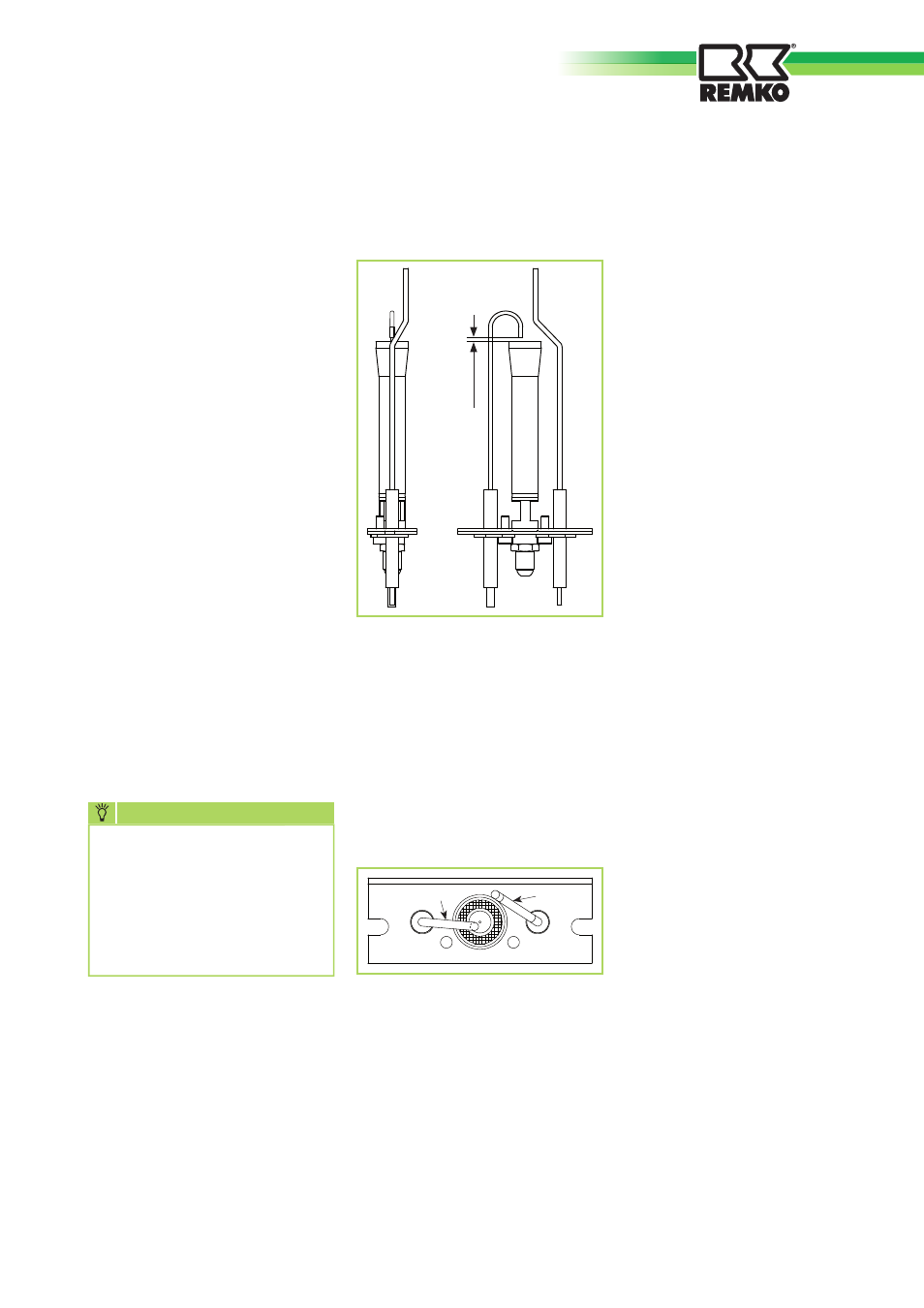
Check the electrodes for correct
seating (see diagram).
It is important that the monitoring
electrode [IO] is located tangential
to the ignition burner head and is
not located within the same.
The ignition electrode [Z] must
discharge towards the outside
edge of the ignition burner at
an adequate distance to the
monitoring electrode.
2) Checking the chimney and
supply air pipes
Visually inspect all pipes and
connecting pieces.
Any dirt deposits that have
accumulated on the end piece
of the supply air pipe must be
removed.
3) Checking and cleaning the
Venturi tube
Remove dirt deposits at the
entrance of the Venturi tube with a
brush or other suitable implement.
Ensure that no dirt falls in to the
Venturi tube.
4) Checking the gas supply
pressure
Ensure that the pressure upstream
of the gas valve corresponds to the
value prescribed for the respective
type of gas.
This check must be carried out
with the unit switched on at
maximum output.
5) Checking the flame monitoring
device
With the unit in heating mode,
close the gas valve and ensure that
fault F1 is indicated. Open the gas
valve again, reset and wait for the
unit to restart.
6) Checking the safety
thermostat(s)
This check must be carried out
with the unit operating in heating
mode.
- Heat the thermostat sensor using
a hot air gun or similar until fault
F2 is indicated.
- Allow the thermostat sensor(s) to
cool down and reset the unit.
- This check must be carried out on
all thermostats in the unit.
Maintenance
2-3 mm
Z
IO
In order to ensure maximum
performance and a long service
life of the units, several checks
must be made once a year and in
any event before the start of the
heating season.
1) Check the condition of the
ignition and monitoring
electrodes as well as that of the
ignition gas burner.
2) Check the condition of the
supply air and chimney pipes as
well as the end pieces.
3) Check the Venturi tube for
clogging.
4) Check the heat exchanger for
fouling.
5) Check the gas pressure
upstream of the gas valve.
6) Check the function of the flame
monitoring device.
7) Check the safety thermostat(s).
8) Check the ionisation flow (> 2
microamperes)
1) Checking the electrodes
Dismantle the ignition burner
completely and clean the gas
system and gas nozzle with
compressed air.
Check the ceramic coating on the
electrodes for intactness.
Carefully remove any oxide
deposits on the metal part of the
electrodes with a very fine emery
cloth.
For steps 1, 2, 3 and 4, the
mains and gas supply to
the unit must always be
interrupted.
Steps 5, 6, 7 and 8 are carried
out with the unit in heating
mode.
NOTE
We reserve the right to make changes to dimensions and design in the interest of technological advances.
s
s
s