Remko gpm, Electrical connection – REMKO GPM 15 User Manual
Page 26
26
REMKO GPM
Electrical connection
Electrical connection of the units
must be made by authorised
specialists (power company
approved) in accordance with the
pertinent regulations.
A main/emergency switch
must be provided at any easily
accessible location within sight
of the unit and protected against
unauthorised use. The switch must
disconnect the unit from the mains
supply in all poles with a minimum
contact opening of 3 mm.
The main/emergency
switch must only be used in
emergency situations or after
extended periods of non-use.
If this switch is used to switch
off the unit during operation,
the electric fresh air fan
cannot cool the combustion
chamber. This can cause
damage to the unit.
ATTENTION
The unit must be provided
with a line-side multipole
disconnector with suitable
electrical protection.
The cable cross-section must
be minimum 1.5 mm².
ATTENTION
The units must be connected
polarised to the mains supply
cable.
Mains supply 230V/50Hz,
minimum cross-section of mains
supply cable 1.5 mm
2
.
Legend rear wall:
= Connector
= Connector socket
= Cable entry fittings
= Unit temperature sensor
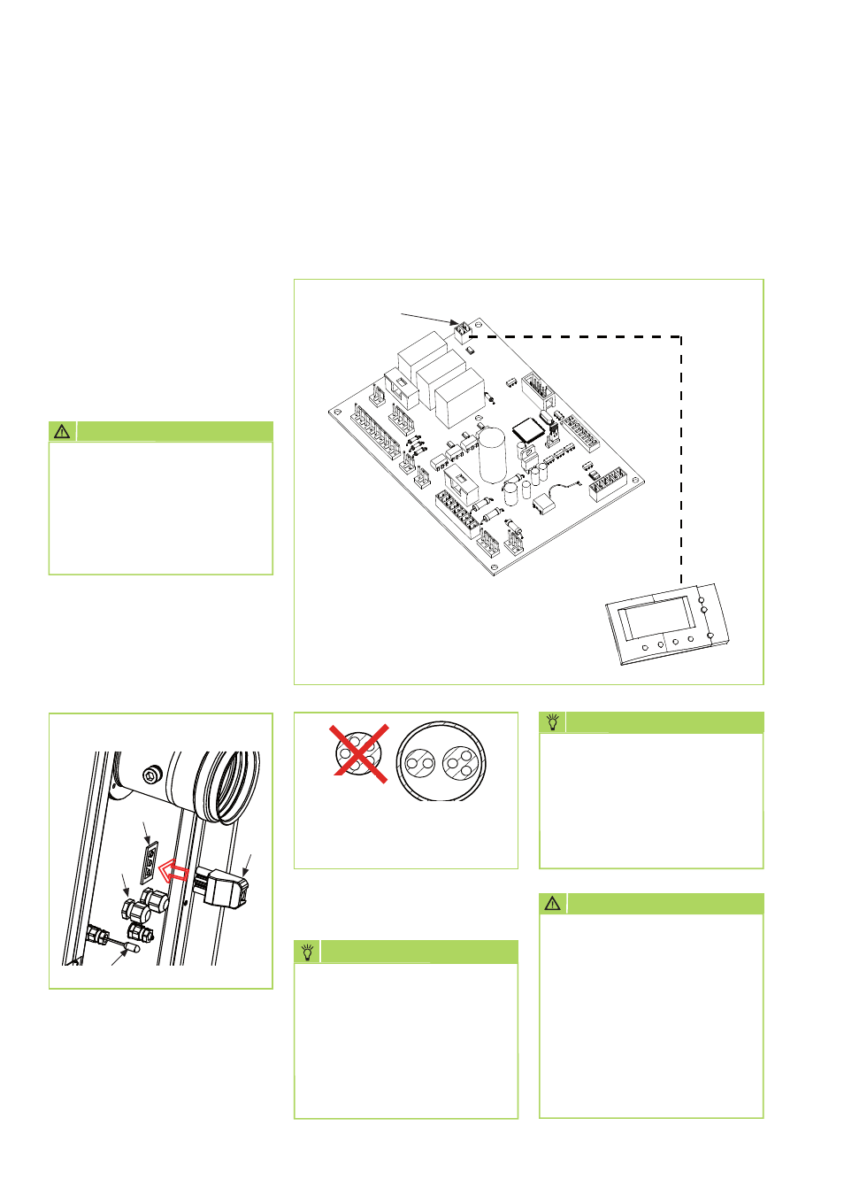
Connecting the temperature control ATR-6 to the control board
Connect the supplied temperature control connector to the locally
installed bus cable, disconnect the two-pin connector [CN] with resistor
from the control board and reconnect the fitted connector with bus
cable.
Electronic temperature
control ATR-6
Control board
ConnectorCN
JA
NEIN!
B
S
B = Bus cable
S = Electric cable
We reserve the right to make changes to dimensions and design in the interest of technological advances.
The use of a multipole
cable simultaneously for
temperature control and mains
supply must be avoided due to
electromagnetic interference.
NOTE
Phase and neutral conductors
must not be confused
during connection under
any circumstances as the
flame monitoring device will
interrupt operation of the unit
for safety reasons.
Fault F1 is indicated.
NOTE
NO
YES