REMKO GPM 15 User Manual
Page 11
11
The faults indicated and stored by
the control board (interlocks) have
the following causes:
F1
- Fault of the flame monitoring
device due to burner ignition
failure; the control board
makes several automatic reset
attempts prior to signalling
the fault.
F2
- Operation of the safety
thermostat.
If the temperature detected
by the thermostat is too high,
the same operates and blocks
operation of the unit.
F3
- Burner fan faulty; the
combustion air fan is faulty or
the signal to the control board
is outside the tolerance range
with respect to the requested
speed.
F4
- NTC1 sensor faulty or not
connected – the sensor value
is outside the measuring
range.
F6
- Control board fault due
to constant and repeated
unsuccessful ignition attempts
of the unit for a predefined
period.
With this fault, the fault
signalling LED located on the
control board also lights up.
F8
- The control board sent the
starting signal to the flame
monitoring device, but did
not receive the started signal;
it is possible that the flame
monitoring device is faulty.
The faults F1 and F2 are caused by
safety devices and are therefore
permanent.
The fault still remains after
switching the mains off and
on again and can only be reset
manually.
The faults F3, F6 and F8 must be
reset manually or by switching the
mains off and on again.
In contrast, fault F4 is self-
resetting:
After clearing the fault, reset takes
place automatically.
The safety information on the
previous pages must be strictly
observed.
In exceptional circumstances, the
units can also be operated briefly
without temperature control.
For this purpose, the jumper on
terminals 7+9 on the terminal
strip M1 in the switchbox must be
removed and a switching device
(e.g. thermostat) connected.
The CR switch on the control
board must be set to OFF (see Fig.
on page 14) and the connector CN
with resistor (see Fig. on page 26)
plugged in.
For this mode, it is neces-
sary to connect at least one
switching device, e.g. room
thermostat in order to be able
to switch the burner on and
off.
NOTE
All information relating to the unit
and faults are now indicated via
LED indicators on the front of the
unit.
The green LED lights up to indicate
that the unit is connected to the
mains.
The red LED lights up to indicate a
fault on the unit.
The cause of the fault can
immediately be identified by the
different flashing/illuminating
states of the red LED:
F1
- LED shows a steady light
F2
- LED flashes twice rapidly
F3
- LED flashes three times
rapidly
F4
- LED flashes four times rapidly
F8
- LED flashes constantly
F6
- Red and green LED flash
alternately
General information
Types of faults
Reset button
A manually operated reset button
on the front of the unit enables
the unit to be reset following faults
F1, F2 or F8 when the temperature
control ATR-6 is not present.
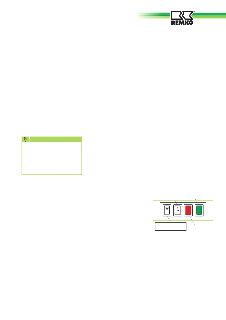
d
Z
Changeover switch
Z
Summer /
d
Winter
Reset button
Green LED
Red LED
Summer/winter switch
A manually operated changeover
switch
d
/ 0 /
Z
on the front
of the unit allows switching
from winter operation
d
to
summer operation
Z
(continuous
ventilation).
In the middle position [0], all
functions of the unit are switched
off.