Figure 80: power cable pin assignment, Table 8: dc power cable pin assignments, Figure 80 – NavCom SF-3050 Rev.I User Manual
Page 87
SF-3050 GNSS Product User Guide
– Rev I
68
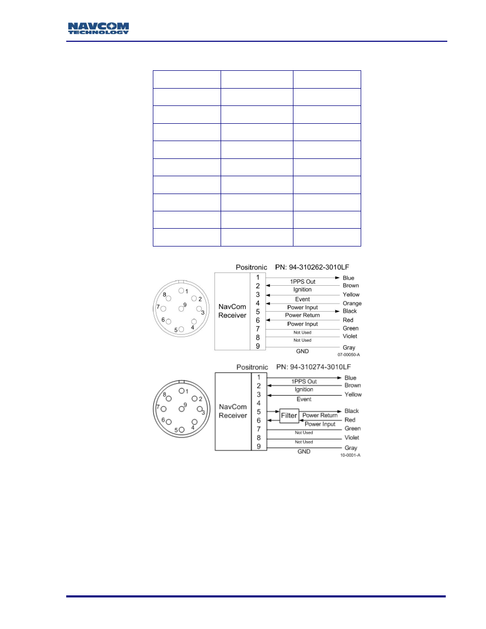
Table 8: DC Power Cable Pin Assignments
Color
Signal
Pin No
Blue
1PPS Out
1
Brown
Ignition
2
Yellow
Event
3
Orange
Power Input
4
Black
Power Return
5
Red
Power Input
6
Green
Not Used
7
Violet
Not Used
8
Gray
GND
9
Figure 80: Power Cable Pin Assignment
The GNSS sensor is protected from reverse polarity with an inline diode. It will operate on
any DC voltage between 9 and 32 VDC, 6 watts typical.
Voltages less than approximately 6VDC will turn the unit off. Voltages from
approximately 5VDC to < 7VDC will create a brown-out. In such case,
power the unit on as follows:
1.
Ignition Pin: Provide power
9 to 32 VDC
This manual is related to the following products: