Event input configuration, Figure 119: event cable wiring diagram, Table 30: event wiring connections – NavCom SF-3050 Rev.I User Manual
Page 154
SF-3050 GNSS Product User Guide
– Rev I
D-135
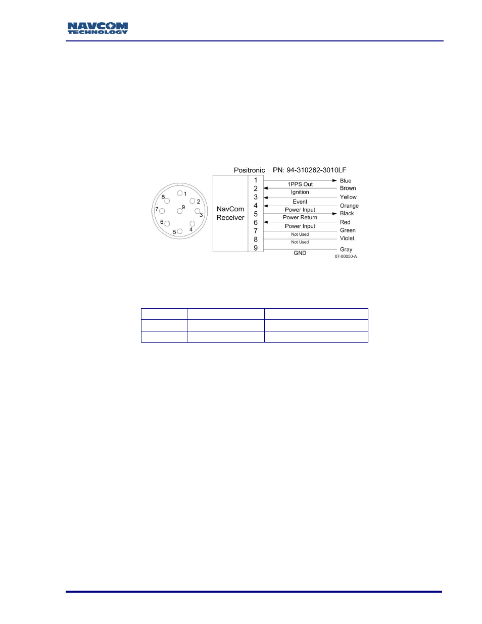
D ............................................................. Event Input Configuration
Figure 119 details the wiring of the supplied Event cable assembly. NavCom part number
P/N 94-310262-3010LF is supplied with earlier SF-3050 production units. P/N 94-310274-
3010LF is supplied with later SF-3050 production units.
Refer to Chapter 3/Event for detailed electrical specifications.
Table 30 details the wiring configuration required for Event pulse sensing.
Figure 119: Event Cable Wiring Diagram
Table 30: Event Wiring Connections
Pin #
Signal Name
Event Sync Wiring
3
Event
Tie Event to Ground
9
Ground
N/A
Once the cable is wired to correspond with the event pulse requirements, configure the
receiver to output the message containing a time mark
– referenced to the time kept
within the receiver indicating when the event is sensed (EVENTLATCH,
EVENTLATCHA).
The EVENTLATCH and EVENTLATCHA messages are described in the
Sapphire Technical Reference Manual (see Related Documents in the
fore-matter).
The Event Input can be triggered on the Rising or Falling edge of the input pulse.
Configuration is possible through the StarUtil 3000 program.