Table 21: acceptable cable lengths – NavCom SF-3050 Rev.I User Manual
Page 116
SF-3050 GNSS Product User Guide
– Rev I
97
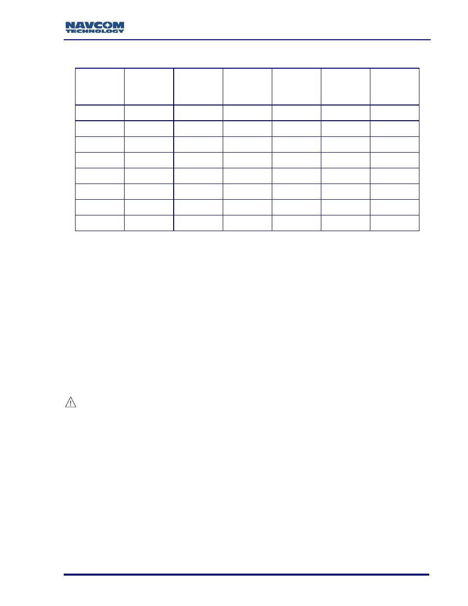
Table 21: Acceptable Cable Lengths
Cable
Type
Atten.
(dB) per
100 Ft.
Cable
Length in
Feet
Loss
in dB
Atten.
(dB) per
100 m
Cable
Length in
Meters
Loss
in dB
RG-58C
19.605
36.00
7.06
64.32
11.00
7.08
RG-142
16.494
43.00
7.09
54.12
13.00
7.04
RG-213
9.564
74.00
7.08
31.38
22.50
7.06
RG-223
17.224
41.00
7.06
56.51
12.50
7.06
LMR600
3.407
207.00
7.05
11.18
63.00
7.04
LMR400
5.262
133.00
7.00
17.26
41.00
7.08
LMR240
10.127
70.00
7.09
33.23
21.00
6.98
LMR195
14.902
47.00
7.00
48.89
14.00
6.85
In-line amplifiers suitable for all GNSS frequencies may be used to increase the length of
the antenna cable, but care should be exercised that tracking performance is not
degraded due to multiple connections, noise from the amplifier, and possible ingress of
moisture and dust to the in-line amplifier. In-line amplifier or splitter devices must pass DC
power from the receiver to the antenna, or source the appropriate voltage and current to
the antenna (see Antenna Specifications). In-line amplifiers may also over-saturate the
receiver front-end if improperly used.
The antenna cable can degrade signal quality if incorrectly installed, or the
cable loss exceeds NavCom specifications. Take care not to kink, stretch,
distort, or damage the antenna cable. Do not place the cable adjacent to
cables carrying electrical power or radio frequencies. In these instances,
attempt to cross cables at 90º angles in an effort to reduce cross-coupling
of RF signals.
Where the GNSS antenna is exposed to sources of electromagnetic
discharge such as lightning, install a properly grounded in-line electrical
surge suppressor between the GNSS sensor and antenna. Install protective
devices in compliance with local regulatory codes and practices. Protective
devices must pass DC power from the receiver to the antenna.