Electrical system, 1 circuit diagram – MovinCool Classic 10 Service Manual User Manual
Page 17
Operation Section
17
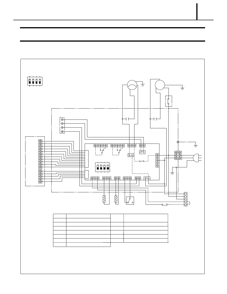
5. ELECTRICAL SYSTEM
5.1 Circuit Diagram
ILL00553-00
TB1
Terminal Block1
TB2
Terminal Block2
RB
Relay Board
MF
Fan Motor
MC
Compressor Motor
CF
Capacitor for Fan Motor
CN
Connector for Option
Drain Pump
CTS
Freeze Protection Thermistor
RTS
Room Thermistor
G
Ground
CB
Control Board
Control Box
On Board
Controller
For Unit Serial Number from February 2011 (0211) to October 2011(1011)
CB
CTS
CN
CN01
G
G
G
1
1
2
1
TB1
RB
Dip Switch
T
1
COM
5
115V
F1
R
T
R
AC115V
1PHASE
60Hz
2
OLC
S
C
CC
CF
2
R
MC
MF
IOLF
AP
Jumper
Line
RTS
Drain Tank SW
CC
Capacitor for Compressor
OLC
Overload Protector
Ground (G)
L-
L+
E-
E+
11
1
5
1
TB2
Output Signal
Fine Alarm
Input
CN23
CN22
CN21
CN24
CN25
CN9
CN8
CN13
CN17
1
1
1
3
CN12
1
3
3
CN11
1
1
ON
2
3
4
2
CN15 52CM
52CT
52ID
520D1
520D2
1
2
4
3
CN16
1
1
1
5
2
1
1
3
5
5
11
HPRS High Pressure Switch
Dip Switch
ON
2
1
4
3
OFF (Default)
#1 : ON: Fan Stop Mode (Fan Auto)
OFF: Fan Operate Mode (Fan On)
#2 : N/A
#3 : N/A
#4 : ON: The Buzzer Sound Disabled
HPRS