MK Products Advanced Color Logic User Manual
Page 19
Advanced Color Logic Owner’s Manual - Page 12
2.9.1.6.5 Low Pulse Time
This time specifies the length of time each high pulse value in this Level.
Valid values are from 0.00 to 9.99 seconds. The Low Pulse time cannot
be longer than the total Level Time, if a longer time is entered, the
program will automatically adjust the entry to match that of the total Level
Time.
2.9.1.6.6 High Current
This is the constant current value of this Level if there is no Current
Slope Time or no pulsing. If sloping exists, then this value is the final
High Pulse Current value for this Level at the end of the Current Slope
Time. If there is current pulsing, then this is the High Pulse Current
value of the Level. Valid values are from 0.00 to 200.00 amps.
2.9.1.6.7 Low Current
This is the constant current value of this Level if there is no Current
Slope Time or no pulsing. If sloping exists, then this value is the final
Low Pulse Current value for this Level at the end of the Current Slope
Time. If there is current pulsing, then this is the High Pulse Current
value of the Level. Valid values are from 0.00 to 200.00 amps.
2.9.1.6.8 High Motor Speed
This is the constant value of the motor speed in this Level if there is
no Motor Slope Time or no Step-Pulsing. If sloping exists, then this
value is the final High Motor Speed value for this Level at the end of the
Motor Slope Time. If there is Motor Step-Pulsing, then this is the value
associated with the High Pulse value of the current. Valid values are
from 0.00 to 10.00 rpm.
If the A/C Welding option is enabled, in the Procedure Options Screen,
the cursor box will move from the weld procedure parameters to the A/C
(Reverse and Straight) weld parameters.
2.9.1.6.9 Low Motor Speed
This is the constant value of the motor speed in this Level if there is
no Motor Slope Time or no Step-Pulsing. If sloping exists, then this
value is the final Low Motor Speed value for this Level at the end of the
Motor Slope Time. If there is Motor Step-Pulsing, then this is the value
associated with the Low Pulse value of the current. Valid values are
from 0.00 to 10.00 rpm.
2.9.1.6.10 Straight Polarity
Normal welding of the ACL is done using Straight Polarity: when the
electrical current flow is from the tungsten electrode (positive) to the
work piece (ground). Valid values are from 0.1 milliseconds to 400.0
milliseconds.
2.9.1.6.11 Reverse Polarity
When using Reverse Polarity, the electrical current flow is form the work
piece (ground switched to positive) to the tungsten electrode (positive
switched to ground). Valid values are from 0.1 milliseconds to 200.0
milliseconds.
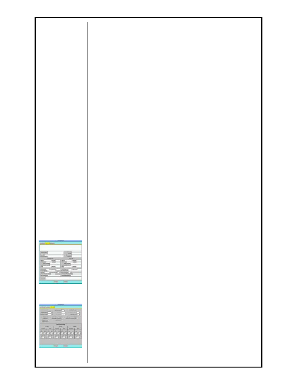
2.9.2 Weld Data Tab
This tab contains many fields used to describe the procedure. This
information is saved with the procedure but is only used for documenting
and printing and is not necessary for welding (See Section G, page 45).
2.9.3 Advanced Tab
This tab is used to enable A/C Welding, set Flying Start values (time and
speed of rotation), set number of tacks and their parameters, enable and
set Weld Start Position, set a value on the amount of scaling allowed to
the operator during a weld, many other advanced features as well as
setting deviation logging and abort tolerances on the weld procedure
See Section G,
page 45 for more
information
See Section G,
page 46 for more
information