MK Products Advanced Color Logic User Manual
Page 12
Advanced Color Logic Owner’s Manual - Page 5
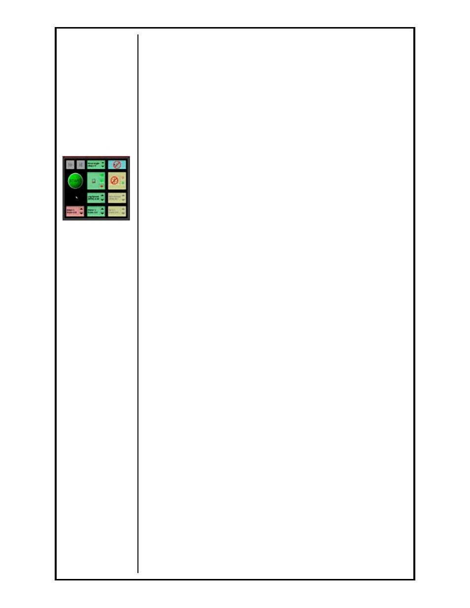
When pushed in (green light on), the Weld Mode is enabled. This will
allow welding to occur during the operation of the procedure.
When pushed out (green light off), the Test Mode is enabled. In the
Test Mode, the entire weld procedure can be operated without welding
occurring.
In the top-middle of the Main Screen (Status Window), either a “W” or a
“T” will appear, depending which mode (Weld or Test) is selected.
2.4 Start Weld
A Weld and a Test Weld operate in the same manner except that in the Test
Mode the welding arc is not initiated. Otherwise, the Test sequence performs
in the same way as a weld sequence including weldhead rotation, system
timing and display.
Once at the weld screen, the operator may press [START] either on the
HHC or at the weldhead control (See Section G, page 43). This will start the
procedure:
The first part of the weld program is the gas Pre-Purge. At this point the
gas solenoid will turn on and gas will begin to flow.
If the Home Pre-Weld option is enabled, the rotor will complete
two revolutions at the higher Calibration Speed (see MOTOR
CALIBRATION), and then stop at home, prior to starting the Pre-Purge.
This is done to update the calibration of the motor. If the rotor was
already at the home position, it will back up slightly then begin its two
revolutions.
If a Flying Start time value is given for the procedure, it will start during
the Pre-Purge time and end at the same time (see Flying Start).
At the end of the Pre-Purge time, the arc will initiate. At the bottom of the
monitor screen, the Voltage Bar Graph will show a bright yellow bar all the
way up the graph (this is the high voltage needed to start the arc). The
amount of current used in establishing the arc is set by Strike Current
parameter in the Weld Procedure Window.
Once the arc voltage and current feedback sense that the arc has been
initiated and is established, the weld procedure will start Level 1 (Up-slope).
In this Level current and rotor speed will initiate and start the welding
arc, commence rotation of the rotor and take the procedure to its
programmed welding parameters.
The actual welding portion of the procedure takes place between the
Up-slope level and the end of the Final Slope level. This is called the
Welding Sequence.
As the weld progresses through the weld levels, the screen shows the
parameter values for the current welding level, including; time left and/
or degrees left in the level, position of the tungsten around the part, the
pulsing current, the resultant pulsing voltage, and the motor speed value
all of which show on their respective bar graphs.
Once the welding sequence is complete, the program will finish in the Final
Slope level.
This level will tail out and taper the weld so that there is no cratering
effect left at the end of the weld, once the arc is extinguished.
Typically, when designing a procedure using APG, the Final Slope current will
slope down while the motor will slope up.
The gas Post-Purge will start immediately after the arc is extinguished at the
end of the Final Slope. It will stay on for as long as programmed.
See Section G,
page 43 for more
information