Signal connection, Pc connection, Quick start – Measurement Computing TempBook rev.3.0 User Manual
Page 9
TempBook User’s Manual,
11-14-00
Introduction and Quick Start 1-3
Quick Start
For those users who wish to get their TempBook up and running as quickly as possible, this section
provides a brief explanation of the steps required. Note: unless already familiar with this type of system,
most users will need to read chapter 2, Installation and Configuration.
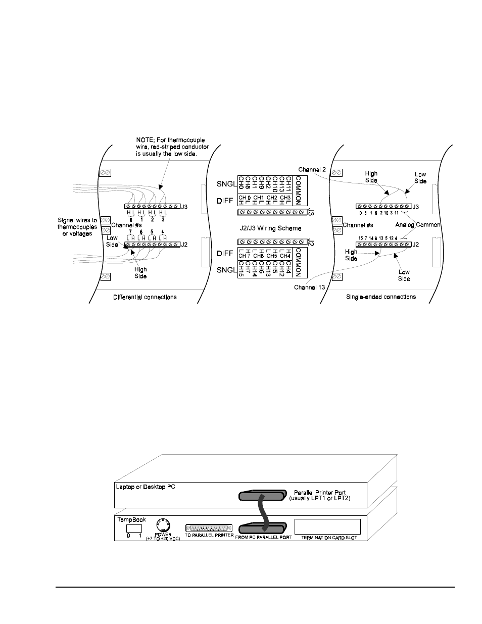
Signal Connection
The thermocouple and voltage input signals are fed to the TempBook through a removable termination
card. To remove this card, rotate the ejector handle with your thumb or finger. Once removed, the
thermocouple or voltage connections should be made as shown in the figure.
Signal Connections, Differential and Single-Ended
Note: When connecting thermocouple or other low-level signals in addition to high-level signals, connect
the low-level signals to the lowest numbered channels with connections in ascending order of signal
magnitude.
The DIP switches located on the termination card connect optional biasing resistors as well as input filters.
•
For thermocouple or other differential inputs, these switches should be closed to provide the required
bias current path.
•
For single-ended inputs these switches can be optionally opened or closed.
For further details, refer to section Termination Card and I/O Connectors in chapter 2.
PC Connection
The TempBook communicates with a laptop or desktop computer through the parallel printer port. Connect
the supplied cable to the computer’s parallel port and the TempBook's parallel port.
PC-to-TempBook Connection