Tbkconfcntr0 – Measurement Computing TempBook rev.3.0 User Manual
Page 65
TempBook User’s Manual
tbkCommand Reference (Standard API) 9-5
tbkConfCntr0
DLL Function
int tbkConfCntr0(uchar config);
C
tbkConfCntr0(unsigned char config);
QuickBASIC
BtbkConfCntr0% (ByVal config%)
Visual Basic
VBtbkConfCntr0% (ByVal config%)
Turbo Pascal
tbkConfCntr0( config:byte ):integer;
Parameters
uchar config
The configuration of Counter 0 (see table below for definitions)
Description
Value
Note
Tc0cHighTermCnt
0x30
High on terminal count
Tc0cOneShot
0x32
Hardware retriggerable one-shot
Tc0cDivByNCtr
0x34
Rate Generator
Tc0cSquareWave
0x36
Square wave
Tc0cSoftTrigStrobe
0x38
Software triggered strobe
Tc0cHardTrigStrobe
0x3A
Hardware triggered strobe
Returns
TerrNoError
- No error
See Also
tbkWtCntr0, tbkRdCntr0, tbkSetTrig
Program References
None
tbkConfCntr0
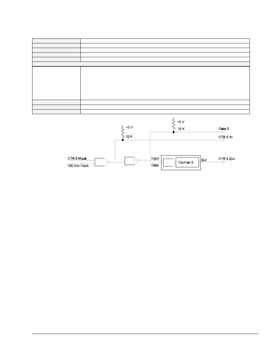
programs the control register of Counter 0 in one of six modes. Counter 0 is a
general purpose counter with input, gate and output lines. The input of counter 0 can be configured
using the ctr0mode parameters of the tbkSetTrig command.
Mode 0, high on terminal count, is typically used to count events. After the initial count value (see
tbkWtCntr0
) is set, the counter will decrement on each pulse of the Counter 0 input. The count
value at any time can be read using tbkRdCntr0. Counter 0 output (pin 2 of P1), which is initially
low, will go high when the counter decrements to 0.
Mode 1, hardware retriggerable one-shot, is used to generate a pulse following the occurrence of a
rising edge of the Counter 0 gate. The output, which is initially high, will go low after the
hardware trigger is received until the count decrements to 0.
Mode 2, rate generator, acts as a divide-by-N counter. The output will be high until the counter
value decrements to 1, when the output goes low for 1 clock pulse before going high again.
Mode 3, square wave generator, is similar to mode 2 except for the duty-cycle. The output will be
high for half of the count value, and low for the other half. If the count value is odd, the
output will remain high for the extra clock pulse.
Mode 4, software triggered strobe, will strobe each time the count value is loaded. The output is
initially high. After the count value is written and has decremented to 1, the output will go
low for one clock pulse before going high again.
Mode 5, hardware triggered strobe, is similar to mode 4 except the strobe is initiated by a hardware
trigger (rising edge of Counter 0 gate).