Inspection, Panel connectors and indicators, Installation, configuration, and calibration – Measurement Computing TempBook rev.3.0 User Manual
Page 11
Installation, Configuration, and Calibration
2
TempBook User’s Manual,
11-16-00
Installation, Configuration, and Calibration 2-1
Inspection
The TempBook components were carefully inspected prior to shipment. When you receive your data
acquisition system, carefully unpack all items from the shipping carton and check for any obvious signs of
physical damage that may have occurred during shipment. Immediately report any damage to the shipping
agent. Retain all shipping materials in case you must return the unit to the factory.
Every TempBook is shipped with the following items:
•
TempBook Data Acquisition System
•
User's Manual
•
Installation CD
•
Calibration Constants Disk
•
Accessory Kit, including: CA-35-2 (2 ft parallel port cable) and an AC Adapter
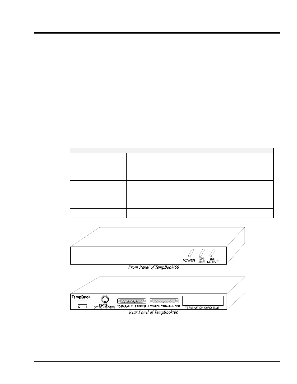
Panel Connectors and Indicators
The TempBook front panel consists of 3 status-indicator LEDs. The rear panel consists of the power
switch, power input, two DB25s for parallel port connection and pass-thru, and a slot to accept the input
termination card. The function of each of these components is described below.
TempBook Panel Connectors and Indicators
POWER SWITCH
This rocker arm switch turns on the DC power to the TempBook when the "1" side
of the switch is depressed.
POWER INPUT
This input connector accepts +7 VDC to +20 VDC.
TO PARALLEL PRINTER
This parallel port can connect to any standard parallel printer. This allows the
user to attach both the TempBook and a parallel printer to the system
simultaneously.
FROM PC PARALLEL PORT
This parallel port connects directly to the PC's parallel printer port. This allows
the host system to communicate with the TempBook.
POWER
This LED is ON when power is applied to the TempBook (and the power switch is
in the ON position). OFF, if power is not present.
ON-LINE
This LED is ON when the TempBook is in an Active state. OFF, when the
TempBook is not enabled or in the printer pass through mode.
A/D ACTIVE
ON during an A/D scan sequence. If the sequence has a small number of steps
and occurs infrequently, this indicator will only flash briefly.
TempBook Front and Rear Panels