Measurement Computing TempBook rev.3.0 User Manual
Page 30
5-2 Programmer's Guide
TempBook User’s Manual
The pacer clock is generated by dividing an internal 1 MHz or 100 kHz clock by a programmable 32-bit
counter. The pacer clock source selection is made by an internal jumper setting, and the counter is
implemented by cascading P1 and P2 of an 8254 counter/timer chip.
The scan sequencer must be loaded prior to any data acquisition. When using the high-level data
acquisition routines (as in the adcex1 example programs), a single command can combine the scan
sequencer setup, trigger selection, pacer clock programming, and data collection. When using the low-level
data acquisition routines (as in adcex2 and adcex3), these operations are broken out into separate
commands.
Note: When connecting thermocouple and other low-level signals in addition to high-level signals, the
low-level signals should be programmed first into the scan sequence with the high-level signals
following in ascending order of signal magnitude.
In addition to the 16 externally available analog input channels, two internal
channels are provided for offset correction and thermocouple cold junction
compensation. The external analog input channels are addressed as channels 0 -
15, the CJC channel is at address 16, and the internal shorted channel is at 18.
The CJC channel must be included in the scan group when reading
thermocouples. This channel reading is used by the thermocouple linearization
functions. The shorted channel, when read at the same gain as an analog input
channel, can be used to remove offset errors present at run time in the analog
electronics. These topics are covered in greater detail in the Thermocouple
Linearization and Zero Compensation chapters.
Besides zero compensation, software compensation can be used to improve
measurement accuracy. The offset and gain errors present after factory
calibration are characterized and recorded within a unit-specific calibration-
constants file. The calibration-constants file is read by the data acquisition
program at run time. The collected ADC data can then be corrected for offset
and gain errors. This topic is covered in greater detail in the Software
Calibration and Zero Compensation chapter.
In addition to analog input, the TempBook provides digital I/O and
counter/timer function. Eight bits each of digital I/O are provided which can be
accessed as register-addressable I/O ports. Additionally, the 8 bits of digital
input can be read as part of the scan group by programming the scan sequencer
with the appropriate channel definition. The digital inputs are then returned
within the ADC data buffer and are right justified within the 16-bit data words.
When the digital inputs are read in this way, the timing relationship between the
trigger event and the analog & digital data is fixed.
A user accessible counter / timer is provided through the P0 port of the 8254.
This port can be configured into one of several modes including one-shot and
pulse-train generation as well as event counting. The clock input to this counter
/ timer port can be taken from an external or internal 100 kHz source. These
topics are covered in greater detail in the Command Reference chapter under the
tbkConfCntr0
and tbkSetTrig commands.
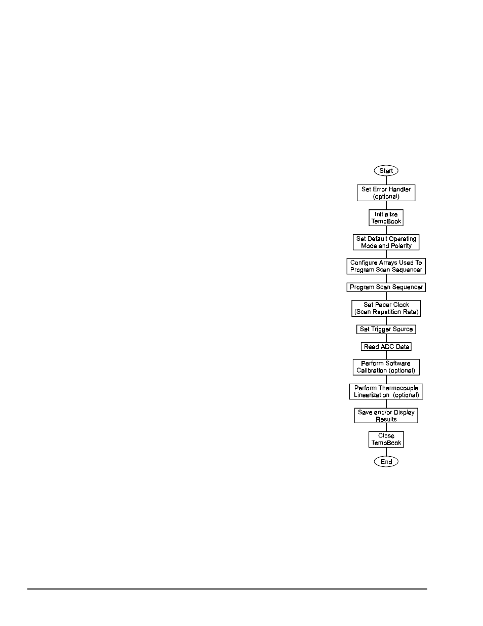
The flowchart diagram shows the operation of a typical TempBook data
acquisition program.
Data Acquisition
Program Flowchart