Internal configuration, Watchdog timer enable/disable (jp8), Time base selection (jp9) – Measurement Computing TempBook rev.3.0 User Manual
Page 13: Hardware installation
TempBook User’s Manual
11-16-00
Installation, Configuration, and Calibration 2-3
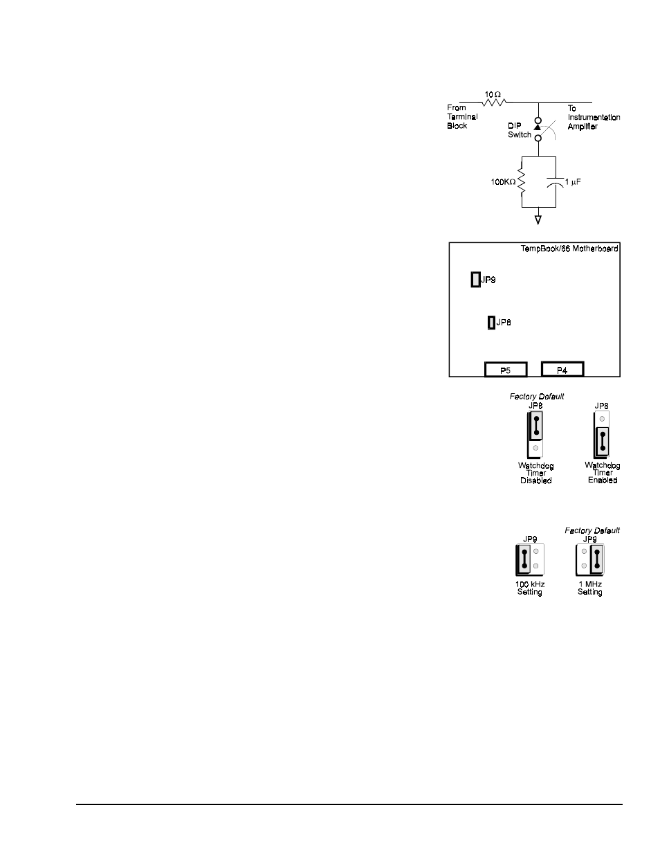
Each of the 16 analog input channels is configured as shown in the figure (also, refer to the appendix for
more information on wiring differential inputs).
The series resistance and shunt capacitance form a single-pole
low-pass filter with a corner frequency of 15.9 kHz. The shunt
resistance provides the bias current path for the instrumentation
amplifier.
When reading thermocouples, these filters should be switched in.
If the filters are not used with thermocouples or any other
differential input, then the user must provide a bias current return
path to signal common. Note that for each differential
channel, two DIP switches need to be set.
Internal Configuration
To open the unit, place the TempBook on a flat surface. Remove
the screw on the top rear of the case, and slide out the top cover.
Reverse this procedure to assemble the unit.
The internal configuration of a TempBook/66 consists of setting
the following jumpers to reflect the desired mode of operation:
•
Time Base (JP9)
•
Watchdog Timer Enable (JP8)
The location of each jumper is shown in the figure.
Watchdog Timer Enable/Disable (JP8)
This 3-pin header allows the elective use of the TempBook watchdog timer
function. If using a printer with the TempBook, the watchdog timer should be
enabled to allow the TempBook to be most reliably reset by the host computer.
Note that enabling the watchdog timer might impede background
measurements. If the user is not going to attach a printer, the timer is optional.
The default setting is Watchdog Timer Disabled. To enable, place the shunt
jumper in the enabled position as shown in the figure. To disable, place the
jumper in the disabled position, as shown.
Time Base Selection (JP9)
This 2×2 header allows the user to select one of two oscillator derived
frequencies to be applied to the pacer clock (8254 P1 & P2). The pacer clock
sets the interval between scans in continuous trigger mode. The two frequencies
are 1 MHz and 100 kHz. The most useful range of clock output frequencies for
the average user would be provided by the 1 MHz setting (the default setting).
Hardware Installation
Connect the TempBook to any PC parallel printer port (female DB25) by unplugging the printer cable and
plugging the male end of the supplied cable (CA-35) into the computer and the female end into the mating
connector on the TempBook. Any printer port (LPT1, LPT2, or LPT3) may be used but should be noted
for use in software installation.
TempBook allows for LPT pass-through for simultaneous data acquisition and printer operation. When
using a printer in the system, attach the original printer cable male DB25 into the mating connector on the
TempBook.
The TempBook may be powered by the supplied AC adapter that plugs into any standard wall outlet or
from an isolated 7-20 VDC source of 1-2 A.
If using the power adapter, plug it into a 120 VAC outlet, and attach the low voltage end to the jack on the
TempBook. Turn ON the power switch, and the POWER LED should be on.