Acquisition configuration – Measurement Computing TempBook rev.3.0 User Manual
Page 21
TempBook User’s Manual
Using TempView (16-bit) 3-3
Pole - The "Pole" column shows the state of the channel polarity which can be either unipolar or bipolar.
The channel polarity can be programmed on a per channel basis. If a cell or block of cells in this column is
selected, a selection box will be displayed above the spreadsheet with the selections "Uni" and "Bi" when
the cell is selected. Double-clicking in one of these cells will toggle the polarity.
Label - The "Label" column contains a descriptive name for the input channel. By default it contains a
label similar to its channel number; however, you can enter a more relevant, descriptive label of 8
characters. This label will be used when selecting a specific channel in the analog trigger and chart
selection lists. This column does not have a selection list above the spreadsheet and does not allow
selecting blocks of cells.
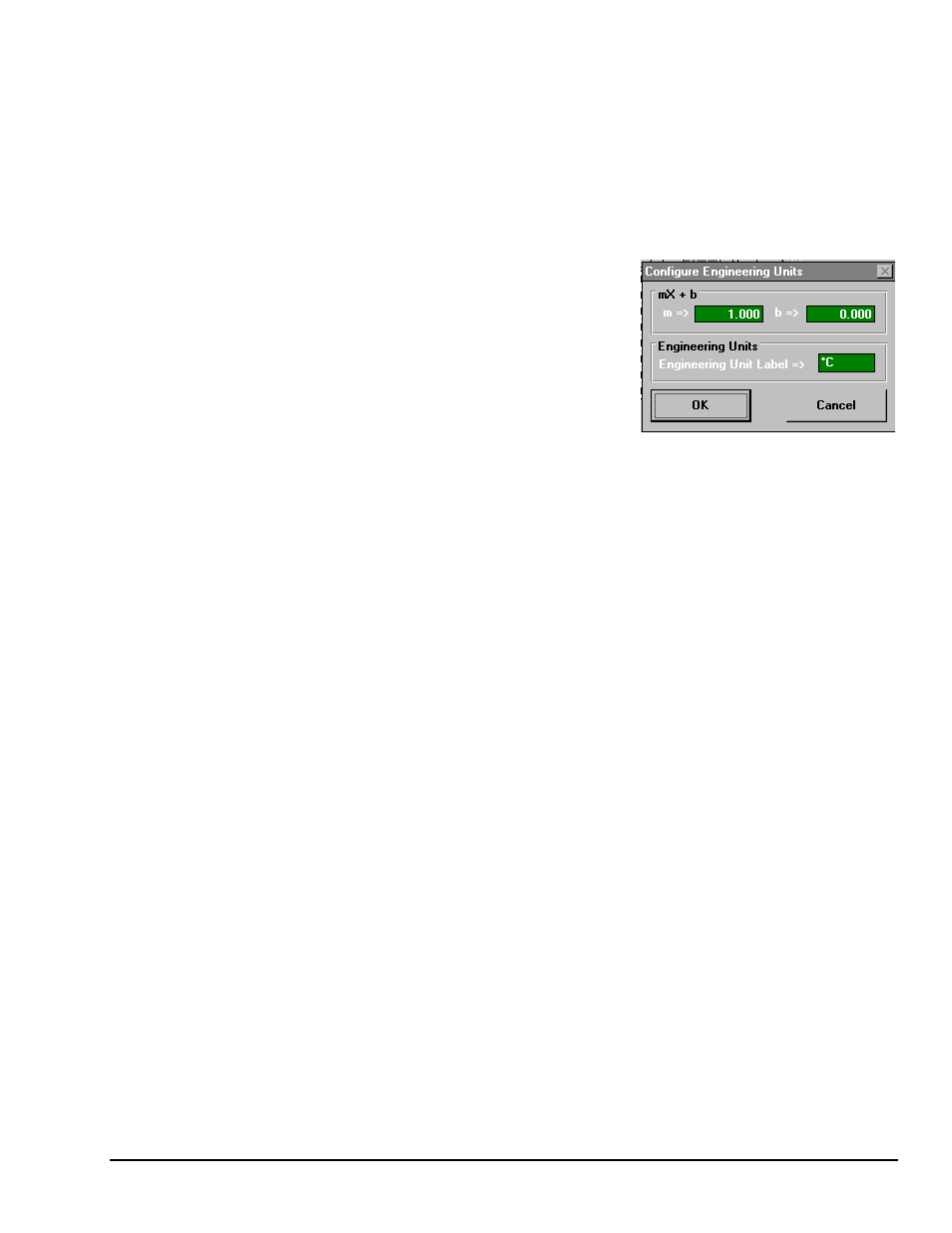
Units - The "Units" column allows you to change the
engineering units of each channel and apply a linear equation to
the data read from the TempBook. When a cell or block of cells
in this column is selected, a selection box is displayed
containing mX+b as well as common engineering units (see
figure). Selecting mX+b will pop up a window that allows the
m and b of this equation and the engineering units label to be
defined. The engineering units will then be displayed in the
"Units" column, and the mX+b equation will be applied to the
reading from the TempBook before the reading is displayed or
written to disk. The X in this equation is the voltage or the degrees in Celsius read back from the
TempBook. For example, if a TempBook channel is configured as bipolar and unity (×1) gain, the default
voltage would be ±5 V. This corresponds to an m of 1, a b of 0 and an engineering unit of V. This could be
changed to millivolts by setting m to 1000 and units to mV. This column could also be used to perform a
software calibration of the TempBook. This is performed by reading known inputs at two different points
of the input voltage range (usually at 0 and full scale) and solving the equation y = mX+b. The full-scale
voltage, which changes according to the gain of the channel, is 5V/gain for bipolar channels and 10V/gain
for unipolar channels.
Reading - The "Reading" column can display the analog input readings of the TempBook. This column
cannot be altered by the user and is enabled by selecting Enable Input Reading Column under the
Acquisition menu. This column will update the readings as fast as the computer will allow. If data is being
written to disk while this column is enabled, it will be updated whenever possible. The spreadsheet cannot
be altered while the input reading column is enabled.
In addition to the analog inputs, there is one 8-bit digital input channel accessible on the termination card.
This high-speed digital input, which is read at the same rate as any analog inputs, can be enabled or disabled
by clicking the "ChanOn" checkbox in the lower right of the analog input spreadsheet.
Acquisition Configuration
The acquisition configuration section of TempView’s main window is just to the right of the analog input
spreadsheet. This section has 5 parts: the Trigger, Scan Frequency, Number of Scans, Signal Conditioning,
and Data Destination sections. These sections allow you to set up all of the acquisition parameters for the
analog inputs and the high-speed digital input channel. The analog acquisition configuration includes
parameters for setting up a trigger source, the scanning frequency after the trigger is satisfied, the number of
scans to take after the trigger, and the file name for the collected data. These settings will be used when an
acquisition-to-disk is started by selecting "Go" under the acquisition menu.
Trigger - The Trigger section selects the source of the trigger. When the trigger is satisfied, the scans are
collected at the selected scan frequency and stored to disk. The sources are: Key Hit, which arms the
acquisition and waits for the user to hit a key; and External TTL, which waits for a falling or rising edge on
the 'trig' input terminal on the termination card.
Sequence Rep Rate - The scan frequency can be set in units of seconds, minutes and hours. Moving the
slide switch changes the rate. The cursor can also be placed in the numeric field and a number can be
entered directly. The maximum scan frequency is dependent on the number of channels that are enabled
and whether or not averaging is enabled. Enabling more channels or enabling averaging will lower the
maximum scan frequency.
Signal Cond Averaging - The Averaging checkbox enables or disables averaging of the analog input data.
Averaging can be used to increase the effective accuracy of a noisy signal. Averaging will increase the