System architecture, Teds composition, Teds table – Measurement Computing IOtech 640 Series User Manual
Page 95
Appendix C
928693
TEDS C-3
System Architecture
The IEEE has partitioned the P1451 standard into five major parts. Each part addresses a different facet or interface of the
project that enables sensor manufacturers to design and build new sensors compatible with all networks. Each part is defined
as follows:
Part 1. Network-Capable Application Processor (NCAP) Information Model
The purpose of this part is to define an object model for smart transducers that connect to a network, and specify a software
interface to work with the transducer’s components. The major components of this model include the NCAP block, function
block, and transducer block. The NCAP processor connects the network to the transducer modules, and each different
network requires a different NCAP physical interface. The smart transducer object model interfaces to the NCAP processor
and to the transducer block. The interface to the transducer block contains details of the transducer hardware in a program
model, and the interface to the NCAP block contains details describing the network protocols.
The NCAP’s primary purpose is to communicate between the STIM and a particular network. The NCAP also computes
calibration corrections and converts between values in metric units and values coming from the STIM’s DACs or going to
the ADCs.
Part 2. Transducer to Microprocessor Communications Protocols and TEDS Format
Part 2 defines the details of a TEDS, including the format for storing data in a small (256-bit to 4 kb) EEPROM and the
interface between the NCAP processor and the transducers. The TEDS contains the information needed by the software to
convert the sensor values such as volts or resistance to physical units, such as force in pounds or acceleration in gs. TEDS is
also part of the Smart Transducer Interface Module. STIM includes the ADCs, DACs, digital I/O, and triggers that connect
to the transducers.
Part 3. Digital Communications and TEDS Formats for Distributed Multi-drop Systems
This part is intended to define the TEDS format and the standard for the interface between multiple transducers in a multi-
drop network. Some of the issues dealing with a multi-drop system include automatically identifying the transducer when it
connects to the bus, and how quickly the system recovers after a short power dropout.
Part 4. Mixed-Mode Communication Protocols and TEDS Formats
Mixed-mode communications deals with the issue of using two-wire I/O, which shares both signal and digital interfaces vs. a
multi-wire system where signal and digital communications are handled on separate wires or ports. Small analog sensors
contain TEDS that let the sensors interface on the network through the same two wires they use for signals. The digital
TEDS data uses the same two wires.
Part 5. Wireless Communication Protocols and TEDS Formats
At the time of this writing, the IEEE P1451 standards committee study group had defined the details of the interfaces for
wireless communications, but not the modules. The intent of the standard is to separate the physical layers from the upper
layers of the protocol stack. Significant progress on the specification is expected in 2004.
TEDS Composition
The data structure for the TEDS works well with a variety of sensor types. Regardless of the sensor’s principle of operation,
the structure contains three major subdivisions; the Basic TEDS; the Standard TEDS (sub-template), and the User Area.
(See Figure C.04, Tables 1, 2, and 3.)
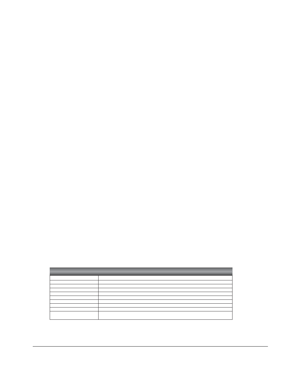
TEDS Table
Meta-TEDS
Provides operational parameters for the transducer
Transducer-channel TEDS
Provides operational parameters for the transducer
Calibration TEDS
Provides calibration coefficients for the transducer
Text-based TEDS
Provides a description of the device for the operator, human readable in XML
Frequency-response TEDS
Provides frequency response for a transducer and associated electronics in a table
Transfer-function TEDS
Provides frequency response for a transducer and associated electronics in algorithm form
End-user, application-specific TEDS User writeable block of non-volatile memory. Contents defined by user.
Commissioning TEDS
User writeable block of non-volatile memory. Intended to provide an identifier for the transducer.
Manufacturer-defined TEDS
Format defined by the manufacturer
Physical TEDS
Defined for the particular physical layer, not included in P1451.0. How to access it is defined by
IEEE P1451.0.
Fig. C.04. Table 1. Basic TEDS Table.