Using accelerometers …… 6-6, Using accelerometers – Measurement Computing IOtech 640 Series User Manual
Page 48
6-6 Analog Signals
878893
640 & 650 Series
Using Accelerometers
Overview
A low-impedance piezoelectric accelerometer consists of a piezoelectric crystal and an electronic amplifier.
When stretched or compressed, the two crystal surfaces develop a charge variation that is related to the
amount of stress, shock, or vibration on the crystal. The amplifier outputs a corresponding signal and
transforms the sensor’s high impedance to a lower output impedance of a few hundred ohms. Note that, in
addition to acceleration, these sensors can also measure pressure and force.
The circuit requires only two wires (coax or twisted pair) to transmit both power and signal. At low
impedance, the system is insensitive to external or “triboelectric” cable noise. Cable length does not affect
sensitivity.
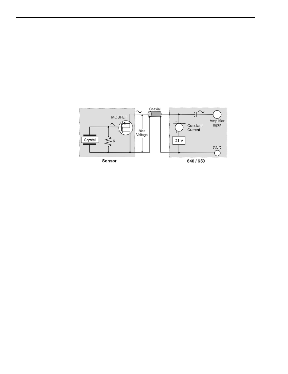
The following figure shows a simple sensor-to-640 [or 650] connection. The voltage developed across R is
applied to the gate of the MOSFET. The MOSFET is powered from a constant current source.
Using a Sensor with a 640 or 650
The MOSFET circuit will bias at approximately 12 V in the quiet state. As the system is excited, voltage is
developed across the crystal and applied to the gate of the MOSFET. This voltage will cause linear
variation in the impedance of the MOSFET and a proportional change in bias voltage. This voltage change
will be coupled to the 640 [or 650] input amplifier through the capacitor. The value of R and the internal
capacitance of the piezoelectric crystal control the low frequency corner. Units weighing only a few grams
can provide high-level outputs up to 1 V/g with response to frequencies below 1 Hz.
Accelerometer Specification Parameters
Noise in Accelerometers
The noise floor or resolution specifies the lowest discernible amplitude (minimum “g”) that can be
measured. There are two main sources of noise as follows:
• Noise from the crystal and microcircuit inside the accelerometer. Some types of crystals, such as
quartz, are inherently noisier than others. A good noise floor is 10 to 20 µV.
• Noise from electrical activity on the mounting surface. Since the signal from the accelerometer is a
voltage, 60 Hz or other voltages (ground loop, etc) can interfere with the signal. The best protection
is to electrically isolate the accelerometer.
Sensitivity
The sensitivity of an accelerometer is defined as its output voltage per unit input of acceleration. The unit
used is “g.” One “g” is equal to the gravitational acceleration at the Earth’s surface, which is
32.2 ft/sec per sec or 981 cm/sec per sec. The output is usually specified in millivolts per “g” (mV/g).
Sensitivity is usually specified under defined conditions such as frequency, testing levels, and temperature.
An example: 100 mV/g at a frequency of 100 Hz, level +1 g, at 72°F. Note that, although a sensor may
have a “typical” sensitivity of 100 mV/g, its actual sensitivity could range from 95 to 105 mV/g (when
checked under stated conditions). Manufacturers usually provide sensor calibration values.