Step 3 - connect data acquisition signal lines – Measurement Computing IOtech 640 Series User Manual
Page 12
Step 3 - Connect Data Acquisition Signal Lines
Step 3 - Connect Data Acquisition Signal Lines
Prior to making signal connections review the Specifications chapter of your user’s manual to ensure that
the input signals do not exceed the specified limits. The manual is included in PDF format on the CD.
Prior to making signal connections review the Specifications chapter of your user’s manual to ensure that
the input signals do not exceed the specified limits. The manual is included in PDF format on the CD.
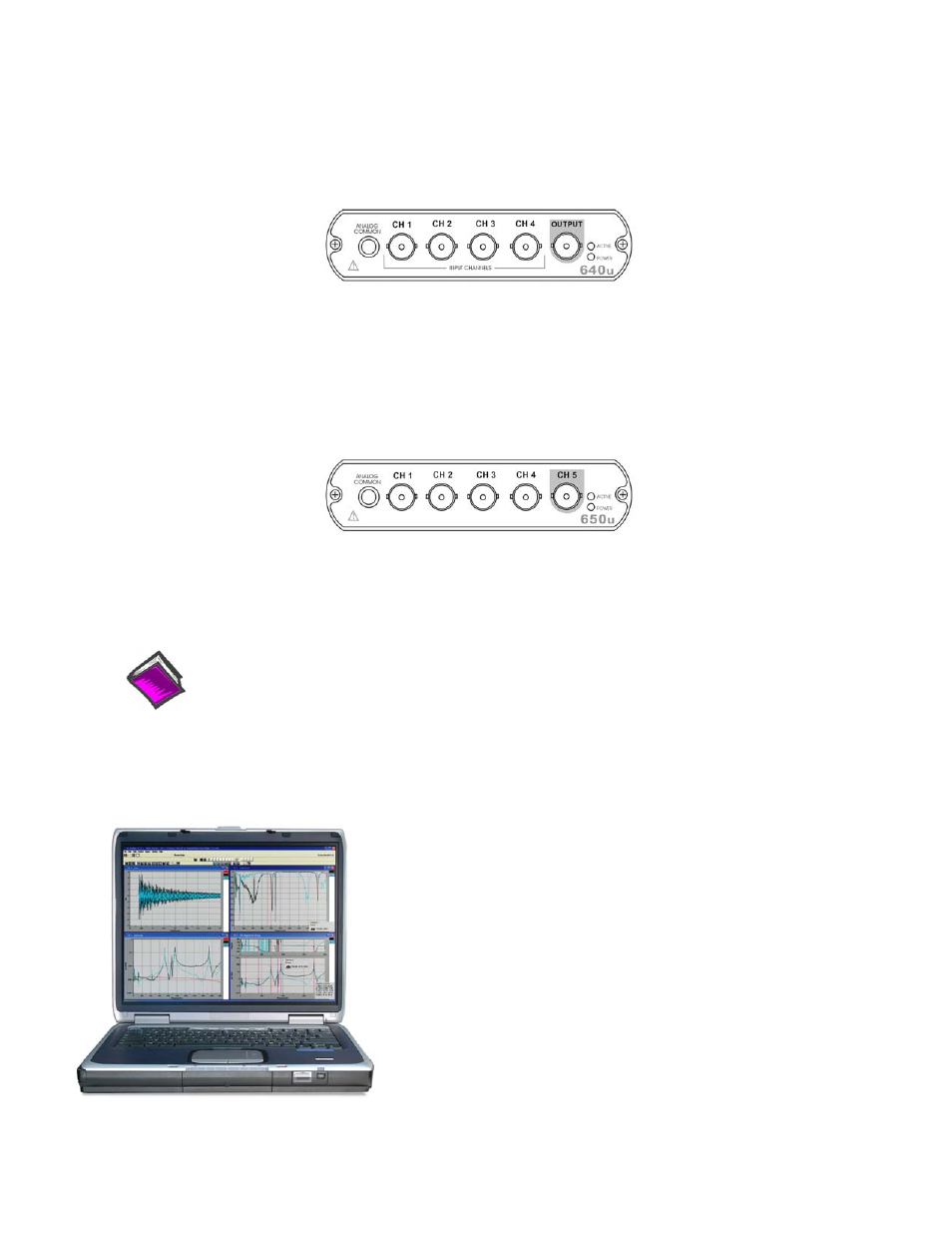
The 640u
The 640u
4 analog channel inputs (CH1 through CH4) via front panel BNC connectors.
1 analog output via the fifth front panel BNC connector.
8 digital I/O lines via rear panel DB9 connector, as discussed in Chapter 3 of the user’s manual.
The 650u
5 analog channel inputs (CH1 through CH5) via front panel BNC connectors.
8 digital I/O lines via rear panel DB9 connector, as discussed in Chapter 3 of the user’s manual.
Reference Notes:
Adobe Acrobat PDF versions of documents pertaining to IOtech 640u and 650u are automatically
installed onto your PC’s hard-drive as a part of product support at the time of software installation.
The default location is the Programs group. It can be accessed via the Windows Desktop Start
Menu.
IOtech, Inc.
25971 Cannon Road
Cleveland, OH 44146-1833
Phone: (440) 439-4091
Fax: (440) 439-4093
E-mail: [email protected]
E-mail: [email protected]
Internet: www.iotech.com
*324540B-01*
324540B-01
Printed in Hungary