6 - analog signals, Analog signals, Introduction – Measurement Computing IOtech 640 Series User Manual
Page 43
640 & 650 Series
878893
Analog Signals 6-1
Analog Signals
6
Introduction …. 6-1
Analog Common …… 6-3
Current Source (IEPE) with Transducer Fault Detection ……. 6-3
Input Coupling …… 6-3
Low-Pass Anti-Aliasing Filter …… 6-4
Transducer Electronic Data Sheet (TEDS) Support
(Requiers eZ-Analyst)
Output BNC (640 units only) …… 6-5
Analog Triggers …… 6-5
Using Accelerometers …… 6-6
Sound & Vibration Sensors – Supplemental Information …… 6-9
Introduction
IOtech 640 and 650 units include circuitry for dynamic analog signal conditioning. The circuitry provides a
way for the units to interface with piezoelectric transducers that include, but are not limited to:
accelerometers, microphones, tachometers, and force/pressure transducers.
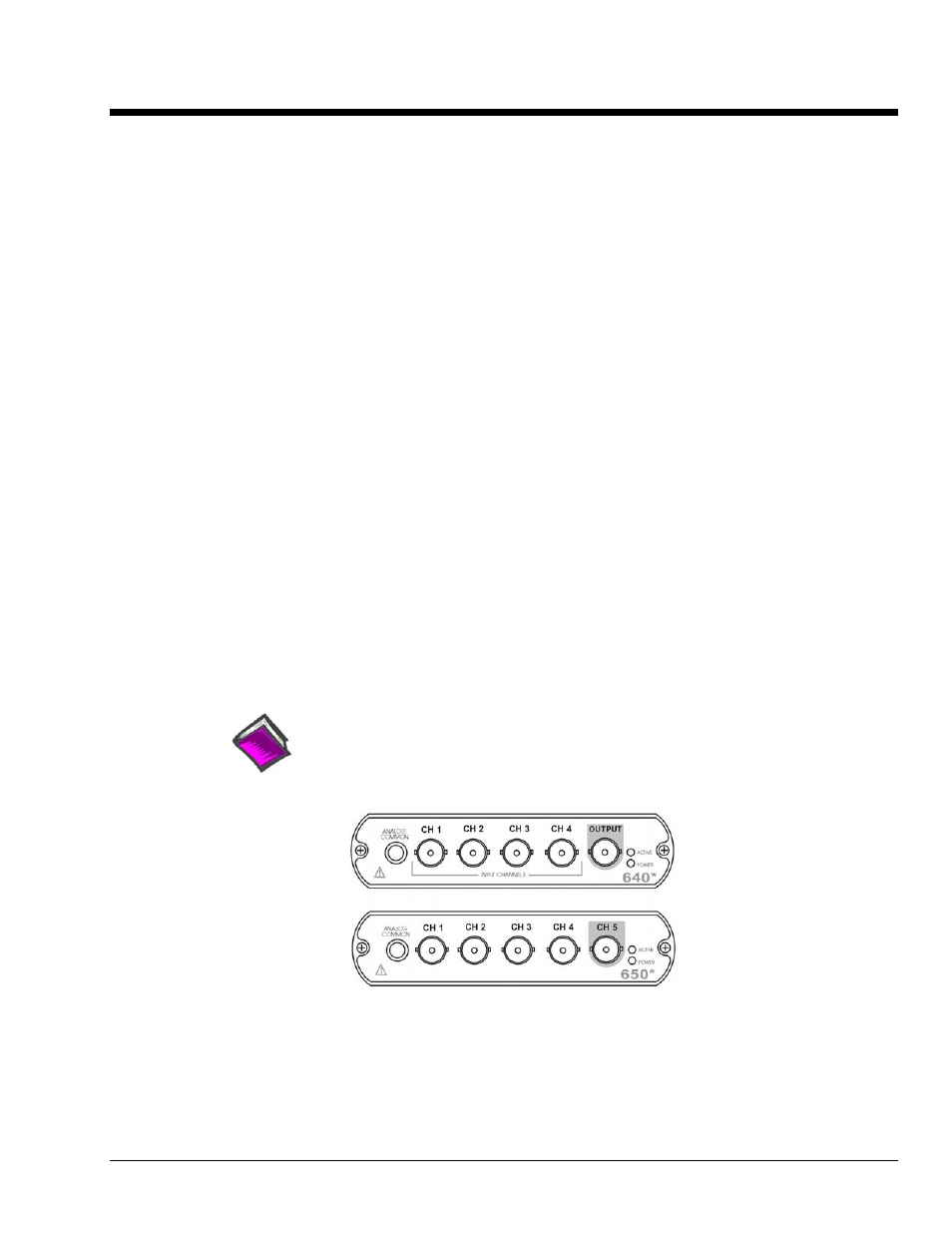
The analog input signal lines, which connect to the dynamic signal conditioning circuit, do so via the front
panel BNCs labeled CH1 through CH4 for 640 models and CH1 through CH5 for 650 models. The center
conductor of these Input Channel BNCs is the signal HI (High). Each BNC shell is connected to the
chassis ground through its own channel-dedicated 1 k
Ω resistor. The Output BNC [applicable to 640 units
only] is discussed later in this section.
Depending on your application, you will need to set several software parameters. Proper settings will
allow the software to organize data to best meet your acquisition needs.
Reference Note:
For detailed information, refer to the applicable software document, e.g., eZ-TOMAS,
eZ-Analyst, eZ-NDT, or eZ-Balance. PDF versions of the document can be accessed from
the data acquisition CD via the
* The actual model number includes an “e” or “u” to indicate Ethernet or USB version.
IOtech 640 and 650 Front Panels