Counters – Measurement Computing LGR-5320 Series User Manual
Page 34
LGR-5320 Series User's Guide
Specifications
34
Counters
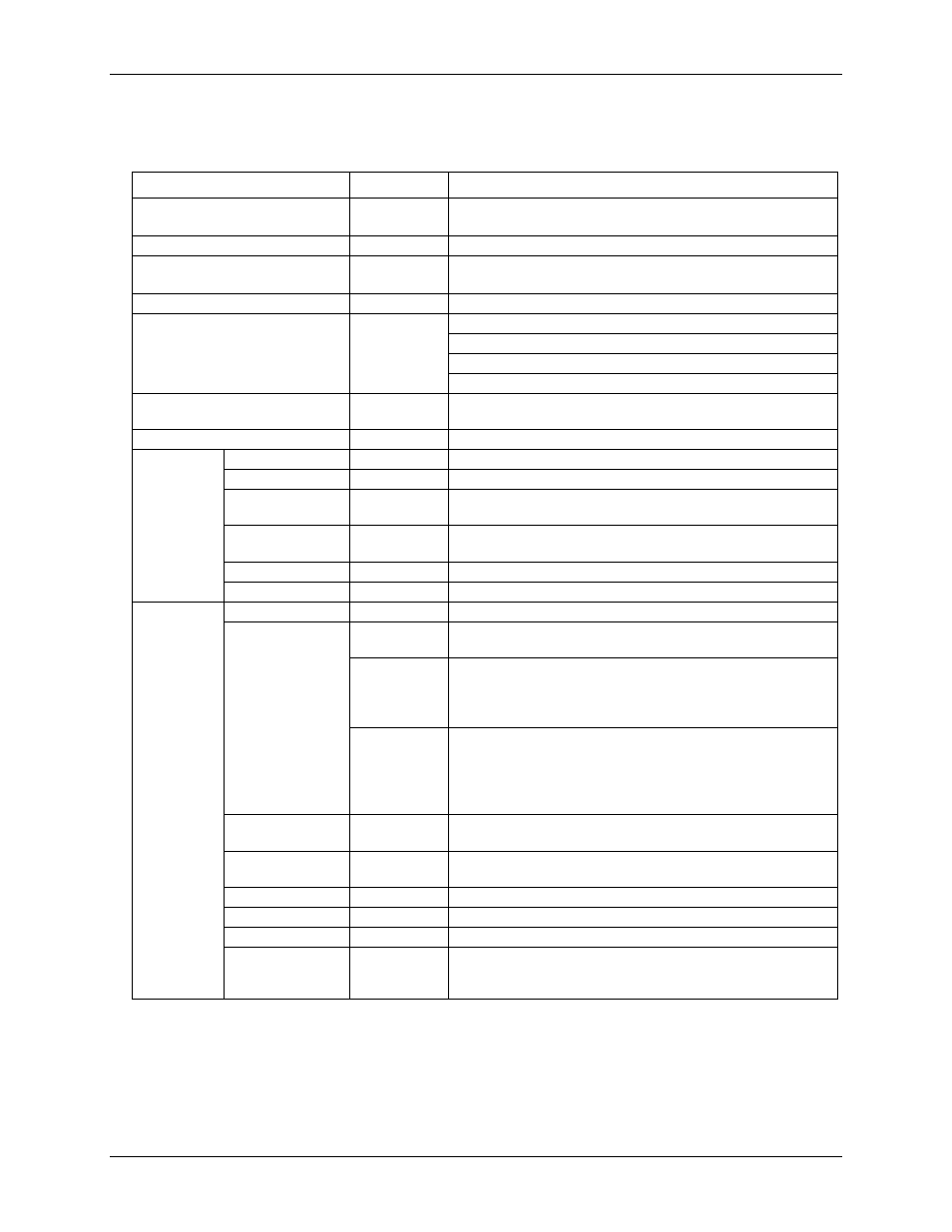
Table 10. Counter specifications
Parameter
Condition
Specification
Counter type
LGR-5325: Conventional
LGR-5327/5329: Conventional and Quadrature (x1, x2, x4)
Number of channels
4
Inputs
LGR-5325: Counter, Up/Down, Gate
LGR-5327/5329: Phase A+/A–, Phase B+/B–, Index +/–
Resolution (programmable)
32-bit or 16-bit.
Count Modes
Up/down counting
Period/frequency counting
Modulo-N
Quadrature counting (LGR-5327/5329 only)
Debounce times (programmable)
16 steps from 500 ns to 25 ms; positive or negative edge
sensitive; glitch detect mode or debounce mode
Timebase accuracy
50 ppm
LGR-5325
only
Input voltage range
0 V to 5.5 V
Input type
TTL
Input
characteristics
49.9 KΩ pull-down resistor
Maximum input
voltage range
–0.5 V to 7.0 V
Input high voltage
2.0 V
Input low voltage
0.8 V
LGR-5327/
5329 only
Receiver type
Quad DIFF receiver
Configuration
Each channel consists of Phase A input, Phase B input and Index
input, with each input switch selectable as SE or DIFF.
DIFF
Phase A, Phase B and Index (+) inputs at user connector routed
to (+) inputs of the DIFF receiver.
Phase A, Phase B and Index (–) inputs at user connector routed
to (–) inputs of the DIFF receiver.
SE
Phase A, Phase B and Index (+) inputs at user connector routed
to (+) inputs of DIFF receiver.
Phase A, Phase B and Index (–) inputs at user connector routed
to ground.
(–) inputs of DIFF receiver routed to +3 V reference.
Common mode
input voltage range
±12 V max
Differential input
voltage range
±12 V max
Input sensitivity
±200 mV
Input hysteresis
50 mV typ
Input impedance
12 k
Ω min
Absolute
maximum input
voltage
DIFF
±14 V max