Screw terminals and associated leds – Measurement Computing LGR-5320 Series User Manual
Page 14
LGR-5320 Series User's Guide
Functional Details
14
IND
button—Cycles through and selectively enables/disables LEDs with each button press. By default, all
LEDs are enabled when the device is powered on.
o
If you press the button when the LEDs are in their default setting, only the LEDs on top of the device
are enabled.
o
If you press the button again, all LEDs are disabled.
o
If you press the button again, all LEDs are enabled.
TRIG/EVENT
button—Forces a trigger if logging has started and the device is waiting for a trigger. Adds an
event to the event log if they are being recorded.
START
button—Starts logging when an SD card with a valid configuration file is in the SD card slot, and
the device is disconnected from a USB port. When a device is logging data, pressing this button stops the
data logging.
SAVE
button—Saves the current logging configuration to a file on the SD card.
LOAD
button—Loads the latest logging configuration file from the SD card.
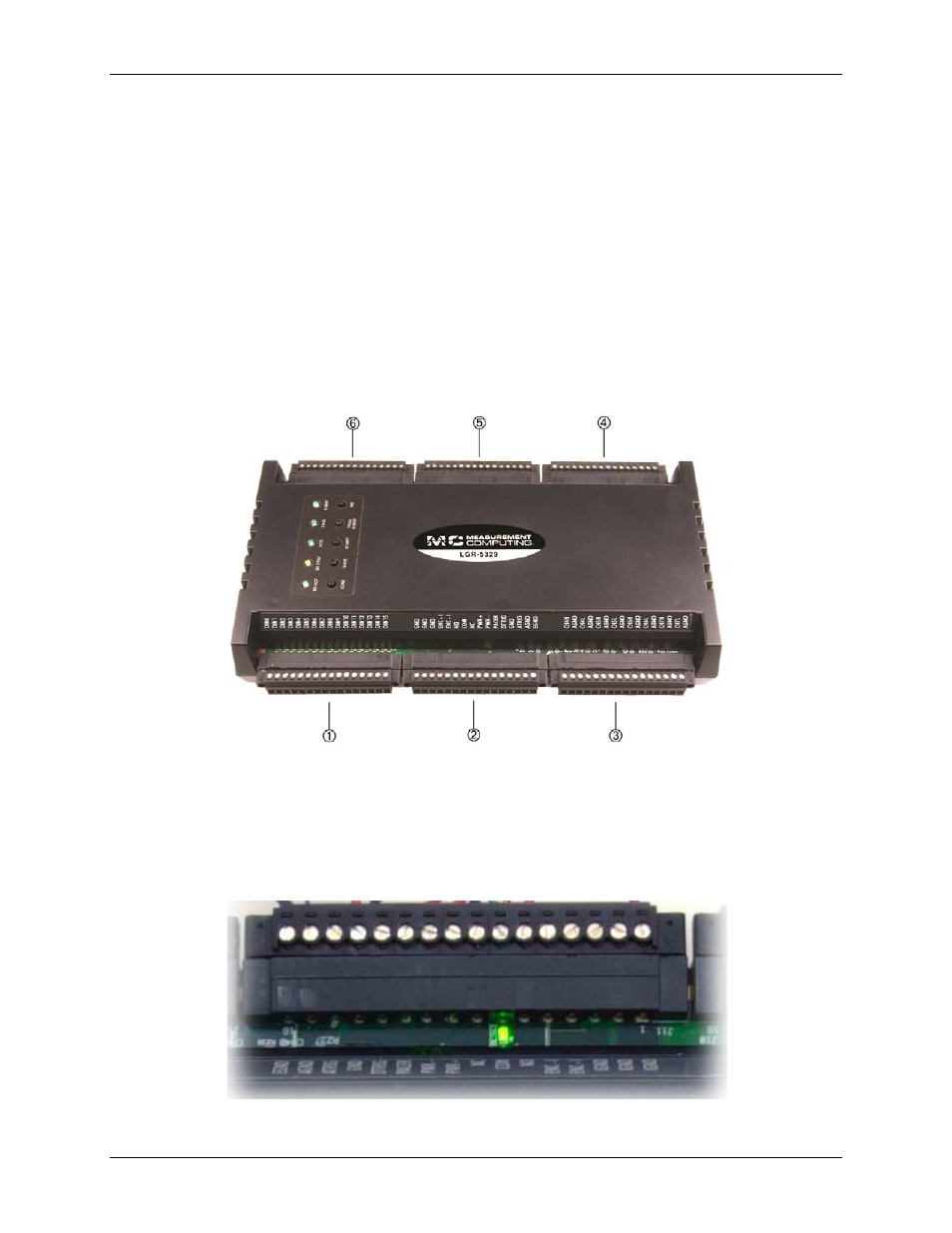
Screw terminals and associated LEDs
1 Digital input terminals and LEDs
4 Analog input 0–3, 8–11 (SE), 0–3 (Diff) terminals and LEDs.
2 Digital trigger, pacer, isolated, earth, and analog ground
terminals, and digital output state LED
5 Counter input 0 and 1 terminals, LEDs, and configuration
switches*
3 Analog input 4–7, 12–15 (SE), 4–7 (Diff) terminals and
LEDs
6 Counter input 2 and 3 terminals, LEDs, and configuration
switches*
* Configuration switches only apply to quadrature counters and
are only installed on the LGR-5327 and LGR-5329.
Figure 6. LGR-5320 Series screw terminals and LEDs
Figure 7. Screw terminal LED on