Counter mode – Measurement Computing LGR-5320 Series User Manual
Page 23
LGR-5320 Series User's Guide
Functional Details
23
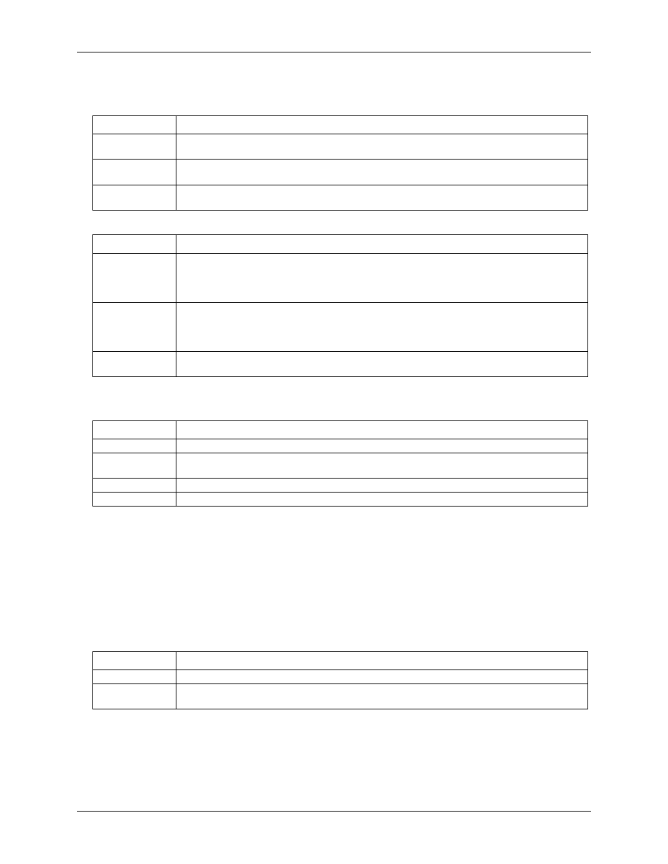
The following options provide different levels of accuracy with respect to the encoder position:
Encoder mode options
Encoder mode
Description
1X
Counts rising edges on phase A. In 1X mode the encoder position is accurate to within
360° ÷ encoder count (for example, if using a 512-count encoder, accuracy would be 360° ÷ 512)
2X
Counts rising edges and falling edges on phase A. In 2X mode the encoder position has double
accuracy (360° ÷ (encoder count * 2)).
4X
Count rising and falling edges on both phase A and phase B. In 4X mode the encoder position has
quadruple accuracy (360° ÷ (encoder count * 4)).
Modulo mode options (Encoder mode)
Modulo mode
Description
Rollover
Counting up: When the maximum count (specified by the modulo number) is reached, the counter
rolls over to 0 and continues counting up.
Counting down: When the count reaches 0, the counter rolls over to the maximum count (specified
by the modulo number) and continues counting down.
Range limit
When counting up: The counter stops when the maximum count (specified by the modulo number) is
reached. Counting resumes if direction reverses or counter is cleared.
When counting down: The counter will count down to 0 and then stop. Counting resumes if direction
reverses or the counter is cleared.
Non-recycle
The counter is disabled if a count overflow or underflow occurs or the modulo number is reached. A
clear command (via software or Index input) is required to re-enable the counter.
Some Encoder mode options are specific to the Index signal. These modes are explained below.
Index input mode options (Encoder mode)
Index mode
Description
No-Op
Ignore the counter index.
Clear
Reloads the count with the modulo number when the counter clears on the rising or falling edge
(software selectable) of the Index signal.
Gate
Use the Index signal to gate the counter.
Latching
Use the Index signal to latch the counter.
Counter mode
You can use a LGR-5320 Series device as a high-speed pulse counter for general counting applications.
Each counter is a 32-bit counter, and accepts frequency inputs up to 10 MHz.
In counter mode, phase A is the primary counter input. You can use phase B to set the count direction in
up/down counting. Use the Index input to gate, latch, or decrement the counter.
LGR-5320 Series devices read counter inputs synchronously as part of the scan list, and support the following
options in counter mode:
Counter mode options
Counter mode
Description
Totalize
General pulse counter.
Clear on read
The counter clears after each synchronous read. The counter value is latched and returned before it
clears.