Functional details, External components, Function buttons and leds (top of case) – Measurement Computing LGR-5320 Series User Manual
Page 12: Chapter 3
12
Chapter 3
Functional Details
External components
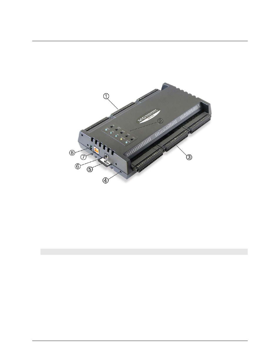
The external components of a LGR-5320 Series device shown in Figure 4 are explained in the following
sections.
1
Screw terminals 1 through 48
5
SD card slot
2
Function buttons and LEDs
6
External power connector
3
Screw terminals 49 through 96
7
USB connector
4
Recessed reset button
8
Power LED (top) and USB activity LED (bottom)
Figure 4. LGR-5320 Series external components
Function buttons and LEDs (top of case)
Each function button on the top of a LGR-5320 Series device case is explained below. All buttons and LEDs are
disabled when a LGR-5320 Series device is connected to a USB port.
SD ACT
LED—Blinks when data is read from or written to the SD card.
Caution! Do not remove the SD card when the
SD ACT
LED is blinking.
SD STAT
LED—Turns on for one second if you attempt an operation without inserting an SD card in the
slot.
The LED blinks when:
o
the logger detects an error on the SD card or SD drive
o
the configuration file on the SD card is invalid
o
a data overrun error has occurred when the device is logging data