External analog trigger, Digital input – Measurement Computing LGR-5320 Series User Manual
Page 32
LGR-5320 Series User's Guide
Specifications
32
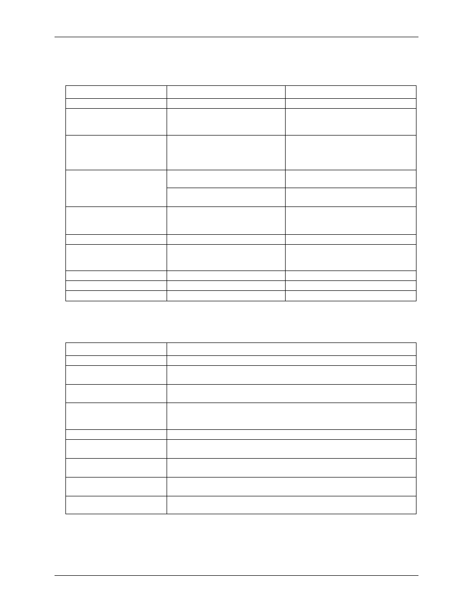
External analog trigger
Table 6. External trigger specifications
Parameter
Conditions
Specification
External analog trigger source
ATRIG input (pin 78)
Analog trigger input ranges
LGR-5325: ±10 V
LGR-5327/5329: ±30 V, ±10 V,
software-selectable
Absolute maximum input voltage
ATRIG_IN to AGND
LGR-5325: ±25 V V max (power on and
power off)
LGR-5327/5329: ±38 V max (power on and
power off)
Input impedance
±30 V range
(LGR-5327/5329 only)
1 M
Ω (power on/off)
±10 V range
10
GΩ (power on)
1 GΩ (power off)
Trigger modes
Configurable for:
Positive or negative slope
Level
Trigger/hysteresis resolution
12 bits, 1 in 4096
Trigger/hysteresis levels
LGR-5325: ±10 V/4096
LGR-5327/5329: ±10 V/4096 or
±30 V/4096, software selectable
Trigger/hysteresis accuracy
±2% of reading, ±50 mV offset
Latency
1.5 µS
Full power bandwidth (–3 dB)
1 MHz
Digital input
Table 7. Digital Input specifications
Parameter
Specification
Number of inputs
16 channels
Input voltage range
LGR-5325/5327: 0 V to 28 V
LGR-5329: 0 V to 30 V
Input type
LGR-5325/5327: TTL
LGR-5329: Industrial
Input characteristics
LGR-5325/5327: 47 k
Ω pull-down resistor, 39.2 kΩ series resistor
LGR-5329: Resistor divider 39.2 k
Ω series resistor and 10 kΩ shunt resistor
connected to IGND
Isolation (LGR-5329 only)
500 VDC min (Note 6)
Maximum input voltage level
LGR-5325/5327: 32 V (power on/off)
LGR-5329: 36 V (power on/off)
Minimum high-level input
voltage threshold
LGR-5325/5327: 2.0 V max
LGR-5329: 10.04 V max
Maximum low-level input
voltage threshold
LGR-5325/5327: 0.8 V min
LGR-5329: 3.85 V min
Event logging (LGR-5327/5329
only)
Change of state, pattern recognition. Event time stamped using real time clock.
Note 5:
The digital inputs are electrically isolated from the analog and digital I/O circuitry. The IGND (isolated
ground) pins should be used as the ground return for the digital inputs.