Measurement Computing LGR-5320 Series User Manual
Page 25
LGR-5320 Series User's Guide
Functional Details
25
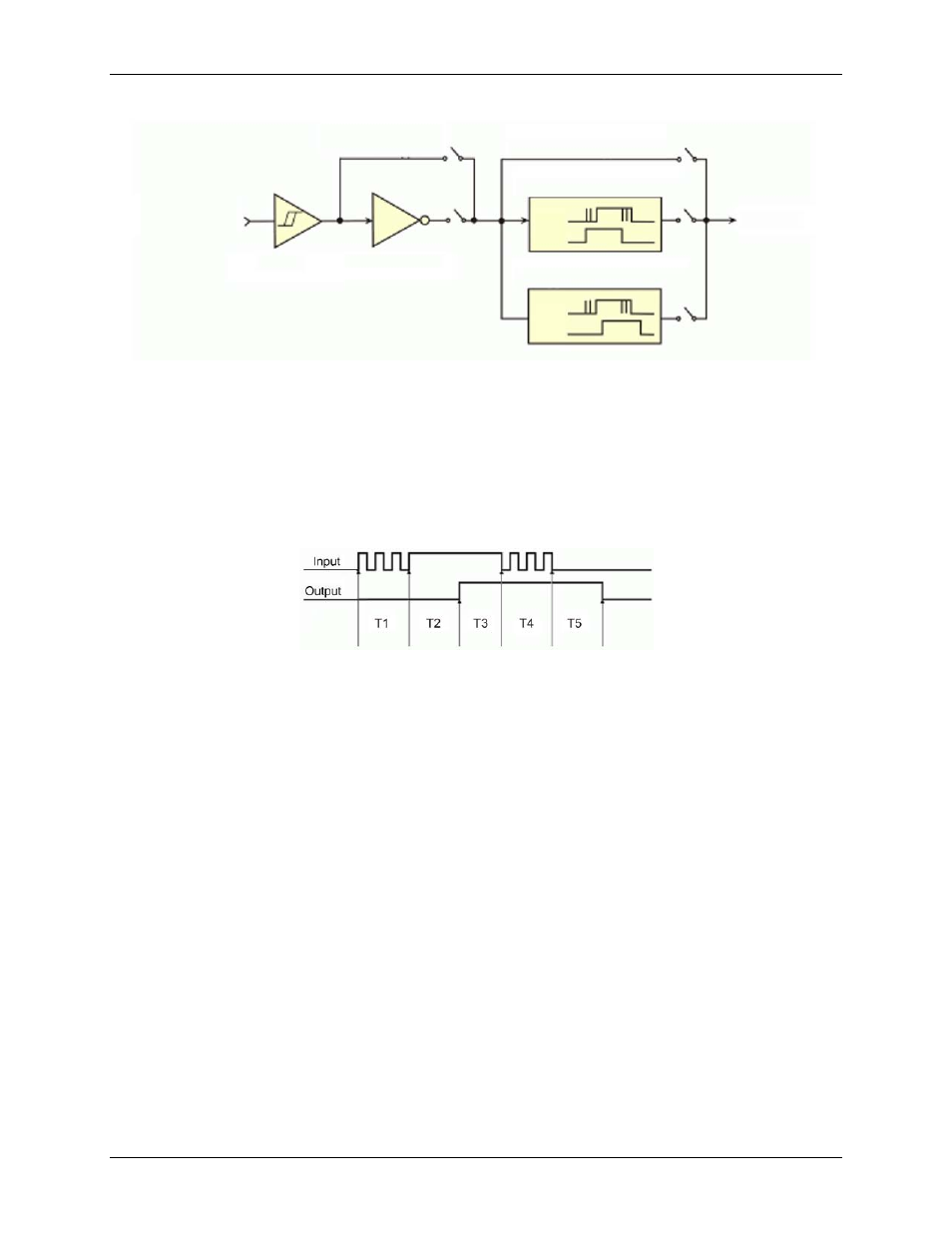
Figure 20. Debounce block diagram
Edge selection is available with or without debounce. In this case, the debounce time setting is ignored and the
input signal goes straight from the inverter or inverter bypass to the counter module.
The two debounce modes are trigger after stable and trigger before stable. In either mode, the selected
debounce time determines how fast the signal can change and still be recognized.
Trigger after stable mode
—In the trigger after stable mode, the output of the debounce module does not
change state until a period of stability has been achieved. This means that the input has an edge, and then must
be stable for a period of time equal to the debounce time. Refer to Figure 21.
Figure 21. Trigger after stable mode
T1 through T5 indicate time periods. In trigger after stable mode, in order for that edge to be accepted (passed
through to the counter module), the input signal to the debounce module is required to have a period of stability
after an incoming edge. For this example, the debounce time is equal to T2 and T5.
T1—In Figure 21, the input signal goes high at the beginning of time period T1, but never stays high for a
period of time equal to the debounce time setting (equal to T2 for this example.)
T2—At the end of time period T2, the input signal has transitioned high and stayed there for the required
amount of time—therefore the output transitions high. If the input signal does not stabilize in the high state
long enough, no transition would have appeared on the output, and the entire disturbance on the input
would have been rejected.
T3—During time period T3, the input signal remained steady. No change in output is seen.
T4—During time period T4, the input signal has more disturbances and does not stabilize in any state long
enough. No change in the output is seen.
T5—At the end of time period T5, the input signal has transitioned low and stayed there for the required
amount of time—therefore the output goes low.
Screw terminals
Buffer
Inverter
Inverter Bypass
Debounce Bypass
Trigger Before Stable
Trigger After Stable
IN
OUT
IN
OUT
To
Counters