Period measurement mode, Pulse width measurement mode, Timing measurement mode – Measurement Computing LGR-5320 Series User Manual
Page 24: Debounce mode
LGR-5320 Series User's Guide
Functional Details
24
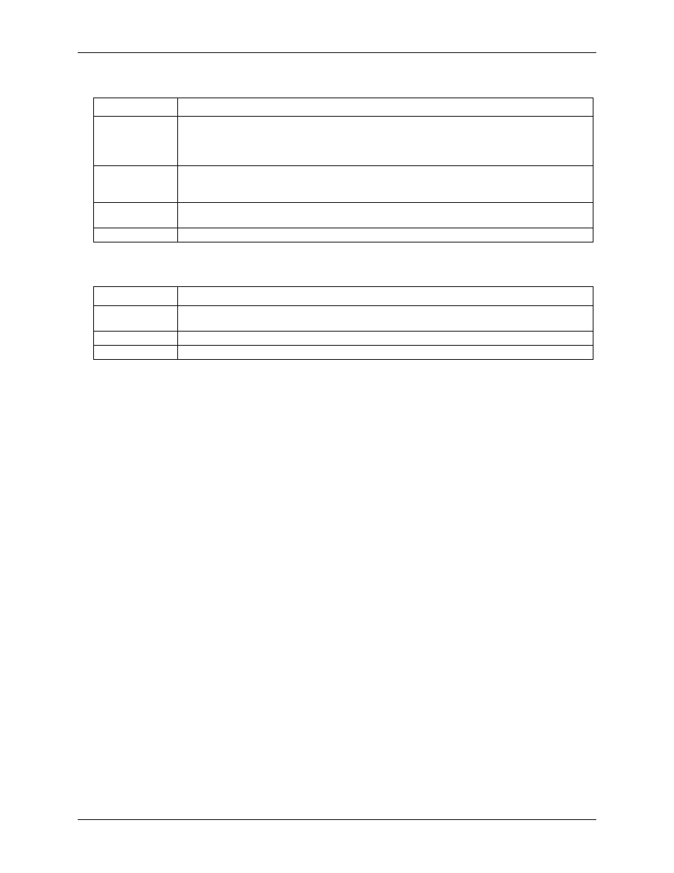
Modulo mode options (Counter mode)
Counter mode
Description
Range limit
When counting up: The counter stops when the maximum count—specified by the modulo number—
is reached. Counting resumes if the direction reverses or the counter reloads.
When counting down: The counter counts down to 0 and then stops. Counting resumes if the
direction reverses or the counter reloads.
Non-recycle
The counter is disabled if a count overflow or underflow occurs, or the modulo number is reached. A
clear command issued through software or through the Index input is required to re-enable the
counter.
Up/down
Up/down counting mode uses phase A as the pulse source and phase B as the direction. The counter
counts up when phase B=1 (high), and counts down when phase B=0 (low).
Modulo-N
Sets the specified modulo number used by the counter mode options explained in this table.
Some counter mode options are specific to the Index signal. These modes are explained in the following table.
Index input mode options (counter mode)
Index mode
Description
Gating
Gating mode allows the Index input to gate the counter. The counter is enabled when the Index signal
is high. When the Index signal is low, the counter is disabled, but holds the count value.
Latching
Latching mode allows the Index signal to latch the count.
Decrement
Decrement mode allows the Index signal to decrement the counter.
Period measurement mode
Use period mode to measure the period of a signal at a counter channel phase A input. You can measure 1X,
10X, 100X or 1000X periods, 16-bit or 32-bit values. Four resolutions are available—to 20 ns, 200 ns, 2 µs, or
20 µs. All period measurement mode options are software-selectable. LGR-5320 Series devices use the 50 MHz
system clock as the timing source, and measure periods from sub-microsecond to many seconds.
LGR-5320 Series devices read counter channel inputs synchronously using period mode.
Pulse width measurement mode
Use pulse width mode to measure the time from the rising edge to the falling edge--or vice versa--on a signal on
a phase A counter input. Four resolutions are available (20 ns, 200 ns, 2 µs, or 20 µs). All pulse width
measurement mode options are software selectable. LGR-5320 Series devices use the 50 MHz system clock as
the timing source. Pulse widths from sub-microsecond to many seconds can be measured.
LGR-5320 Series devices use read counter channel inputs synchronously using pulse width mode.
Timing measurement mode
Measures the time from a rising or falling edge on phase A to a rising or falling edge on the Index inputs.
Debounce mode
LGR-5320 Series devices have debounce circuitry, which eliminates switch-induced transients that are typically
associated with electromechanical devices including relays, proximity switches, and encoders.
All debounce options are software selectable. You can select a debounce time, debounce mode, and rising-edge
or falling-edge sensitivity. LGR-5320 Series devices use can debounce each channel with 16 programmable
debounce times in the range of 500 ns to 25.5 ms.
Two debounce modes (trigger after stable and trigger before stable) and a debounce bypass are shown in
Figure 20. The signal from the buffer can be inverted before it enters the debounce circuitry. The inverter is
makes the input rising-edge or falling-edge sensitive.