Digital pattern trigger, Digital i/o – Measurement Computing LGR-5320 Series User Manual
Page 21
LGR-5320 Series User's Guide
Functional Details
21
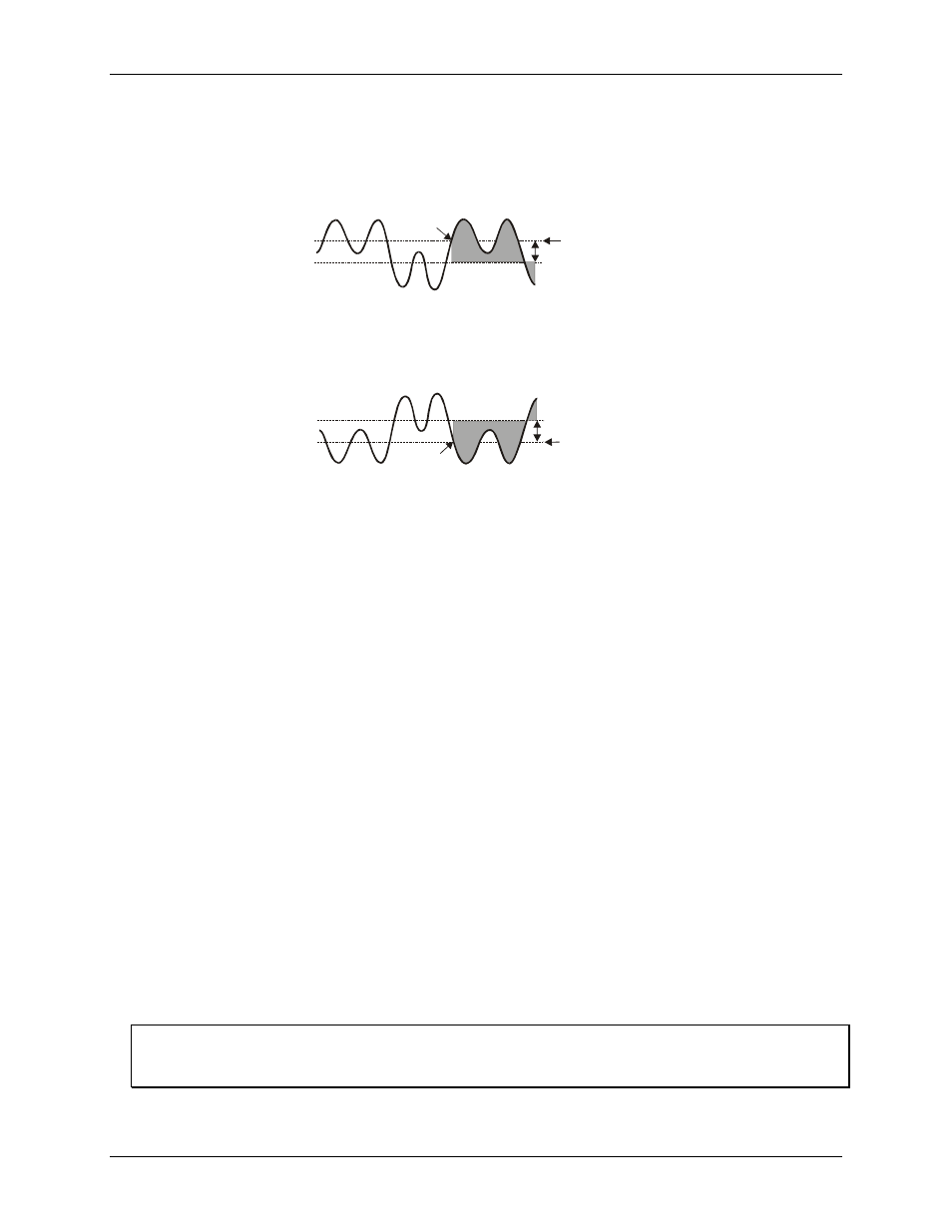
Rising-edge-with-latch trigger
—This trigger becomes valid like a rising-edge trigger—when the signal level
goes above the threshold after first being below the hysteresis range. However, the rising-edge-with-latch
trigger does not become invalid, regardless of the signal level, until the acquisition is complete. Rising-edge-
with-latch is used to trigger after the channel has reached the threshold, rather than just while the channel is
above the threshold.
Figure 18: Rising slope, latched duration, edge initialization
Falling-edge-with-latch trigger
—This trigger is the reverse of the rising-edge-with-latch trigger—it becomes
valid after the signal level has been above the hysteresis range and then goes below the threshold. The trigger
remains valid until the acquisition is complete.
Figure 19: Falling slope, latched duration, edge initialization
Digital pattern trigger
The digital pattern trigger is an expanded digital-trigger that starts collecting data when a 1 to 16-bit digital
pattern—that you define with pattern and mask settings—matches the bit pattern on the digital input connector.
This type of trigger is useful when trying to capture noise, vibrations, or some other physical disturbance that
occurs at a particular point in a digitally-sequenced process, such as a relay-logic-control system.
Two settings control this trigger operation—the condition and the mask.
The polarity setting allows the following choices:
Rising edge/high level (equal to)—Triggers when there is an exact pattern matches of "1s" and "0s"
between the compared patterns.
Falling edge/low level (not equal to)—Triggers on any change of "1s" and "0s" between two patterns that
previously matched.
The mask setting can set any of the input bits to don’t care (X), which excludes that bit from the polarity
comparison.
Digital I/O
You can connect up to 16 digital inputs to a LGR-5320 Series device. Each digital input is electrically isolated
from the host computer and from the LGR-5320 Series analog and counter circuits.
You can configure these inputs to detect events based on change of state or pattern recognition. These are the
same bits used for a digital pattern trigger (refer to the Digital-pattern trigger section above)
The digital inputs have a wide input voltage range of 0 V to 30 V.
The digital output is an alarm implemented as a single Form C relay on the
NC
(normally closed),
COM
(common), and
NO
(normal open) screw terminals.
You can configure the relay to energize when the trigger condition is met and data is being recorded.
Always use the IGND screw terminals with digital inputs with the LGR-5329
Because the digital inputs on a LGR-5329 are electrically isolated from the analog and digital I/O circuitry,
always use the IGND (isolated ground) screw terminals as the ground return for digital inputs.
Threshold
Hysteresis
Trigger
Threshold
Hysteresis
Trigger