Measurement Computing LGR-5320 Series User Manual
Page 13
LGR-5320 Series User's Guide
Functional Details
13
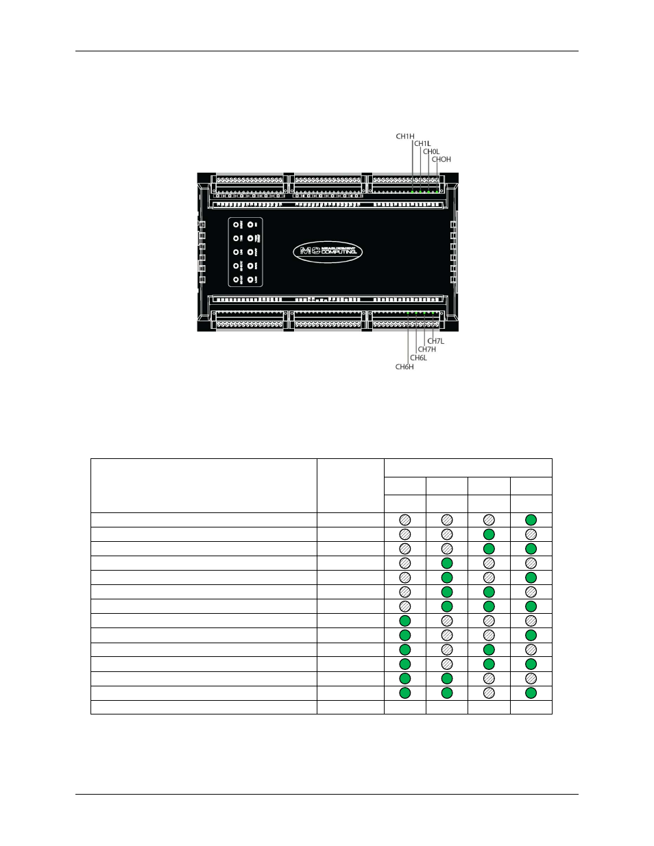
When the
SD STAT
LED blinks to indicate an error, the four LEDs for analog channels CH0H, CHOL,
CH1H, CH1L, and the four LEDs for analog channels CH6H, CH6L, CH7H, and CH7L blink in a pattern
that represents a numeric error code. Press any button on the top of the case to acknowledge the error and
stop the LEDs from flashing.
Figure 5. LGR-5320 Series error code LEDs
For example, if you attempt to log without an SD card inserted in a LGR-5320 Series device, the
CHOH
and
CH7L
LEDs both blink, representing binary code 0001.
All SD STAT errors and corresponding analog input LED blink codes are explained below.
LGR-5320 Series error descriptions and codes
Error
Blink code
(binary )
LED pattern
CH1L
CH1H
CH0L
CH0H
CH6H
CH6L
CH7H
CH7L
Card not present
0001
Card not mounted
0010
Card write protected
0011
File system error
0100
FLASH write error
0101
Overrun – pacer
0110
Overrun – FIFO
0111
Overrun – events
1000
DMA error
1001
Card full
1010
File reached max size
1011
Log configuration error
1100
Log configuration not valid for device
1101
LOG
LED—On when the device is logging. Off when the device is idle.
TRIG
LED—Turns on when the acquisition is triggered.
EVENT
LED—Blinks when an event occurs.