Screw terminal led functions, Signal connections, Analog input – Measurement Computing LGR-5320 Series User Manual
Page 15
LGR-5320 Series User's Guide
Functional Details
15
Screw terminal LED functions
The functions of the LEDs associated with screw terminals are explained below.
The LED for each active digital connection is on when voltage is detected.
The LED near the
PWR+
terminal is on when the relay is energized
The LED for each analog input terminal is on if the associated channel is in the scan list.
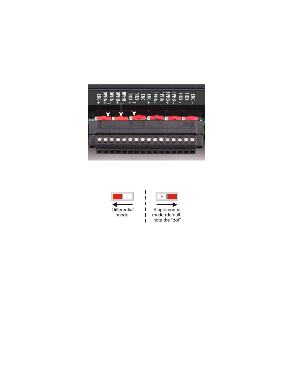
On the LGR-5327 and LGR-5329, you can configure the encoder counter inputs as single-ended or differential
mode using the switches that correspond to each pair of phase A, phase B, and Index terminals (see Figure 8).
Figure 8. LGR-5327 and LGR-5329 counter channel input terminals and input mode switches
To configure a counter channel for single-ended mode, slide the switch to the right. Note that the "dot" is
visible on the switch when a channel is configured for single-ended mode.
To configure a counter channel for differential mode, slide the switch to the left.
Figure 9. Channel input mode switch settings
Figure 9 assumes a board orientation with the USB connector on the right.
Signal connections
Analog input
LGR-5320 Series devices have a 16-bit, multiplexed A/D that supports up to 16 single-ended or up to eight
differential analog inputs.
For the LGR-5325, the maximum throughput sample rate is 100 kS/s.
For the LGR-5327 and LGR-5329, the maximum throughput sample rate is 200 kS/s.