K-Patents SeedMaster 2 User Manual
Page 84
11 COMMUNICATION
84
84
2. XOR CRC high with the 1
st
data byte, the result remains in the CRC word.
3. Shift CRC 1 bit right.
4. If the most significant bit of the CRC was 0 before the shift, the next step is step 3 (go to step 3).
5. If the least significant bit of the CRC was 1 before the shift (1 was shifted out) then XOR CRC and the
CRC calculation polynomial A001 (hex), the result remains in the CRC word.
6. Repeat steps 3 & 4 until 8 shifts.
7. XOR CRC and the next data byte, the result remains in the CRC word.
8. Repeat 3-7 steps with all data bytes.
9. The result is the CRC code to be sent or verified.
The implemented MODBUS commands:
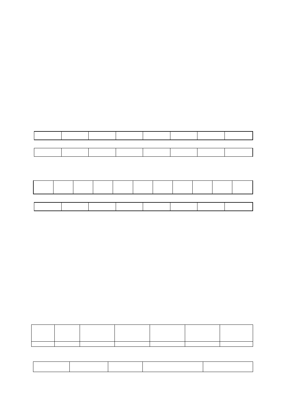
Read multiple MODBUS registers command, function code : 03(03h):
Query:
A
F
RAH
RAL
RNH
RNL
CH
CL
Response:
A
F
BN
D1
…
DN
CH
CL
Write multiple MODBUS registers command, function code : 16 (10h):
Query:
A
F
RA
H
RA
L
RN
H
RN
L
BN
D1
…
CH
CL
Response:
A
F
RAH
RAL
RNH
RNL
CH
CL
where
A
– slave address
F
– function code
RAH, RAL – starting address of the MODBUS registers, order: high byte first
RNH, RNL – number of the MODBUS registers, order: high byte first
BN
– number of the data bytes sent (0..255)
D1….Dn
– n data bytes, n=BN*2, order: high byte first
CH, CL
– CRC control code, order: high byte first
Examples
•Function code: 3 (read), RTU mode
Read the first 32 data (64 registers, i. e. 128 bytes) from the „read data” table of the 1
st
Crystallizer of
SeedMaster 2 having the station address 17 (11h):
Query:
Slave
address
Function
code
1
st
register
address
(high byte)
1
st
register
address
(low byte)
No of
registers
(high byte)
No of
registers
(low byte)
CRC
code
(2 bytes)
11h
03h
00h
00h
00h
40h
CRC
Response:
Slave
address
Function
code
No of the
bytes sent
Data bytes
CRC
(2 bytes)