2 process inputs and outputs, 3 digital communication – K-Patents SeedMaster 2 User Manual
Page 25
4
TECHNICAL DATA, MOUNTING AND ELECTRICAL CONNECTIONS
25
25
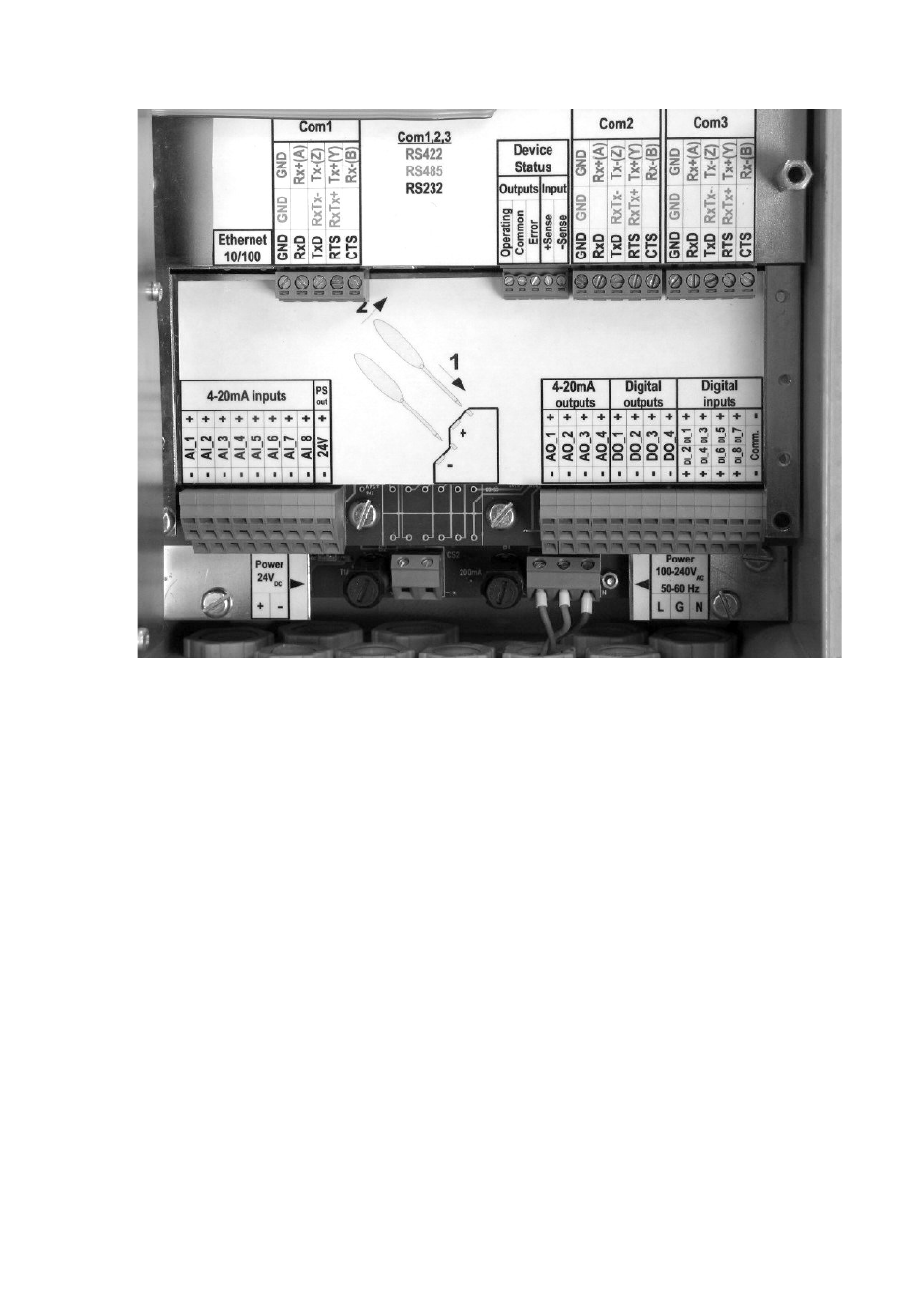
Fig. 4.2 Electrical connections
There are two screw-type terminals for power connection in the bottom of the enclosure (see Fig. 4.2). The
one on the right side has 3 terminals (L: line, G: ground, N: neutral) to connect the AC power input, while the
one on the left has 2 terminals with polarity markings for 24 V DC input. Both power inputs have their
dedicated fuses.
4.2.2 Process inputs and outputs
Process inputs and outputs use printed circuit spring cage terminal blocks. There are 2 connection points
(polarity is marked) per terminal block. Just above the power input level on the left side there are terminals for
8 analog input (AI) channels (0-20, or 4-20 mA, keyboard selectable) and a 24 V DC output (PS out) to
supply power for transmitters (max. load: 200 mA).
On the same level on the right side similar terminals for 4 analog output (4-20 mA) channels (AO, channels
1…4) are located. These are followed by 4 digital output channels (DO, channels 1…4), then by 8 digital
inputs (DI, channels 1…8). The digital inputs have their common terminal point (common) in the rightmost
position. All terminal points have their appropriate polarity markings.
4.2.3 Digital communication
There are screw-type terminals on the highest level (Fig. 4.2) for 3 serial communication ports (Com1, Com2,
Com3). Their connection points are colour-coded according to the selected type of communication (black:
RS232, red: RS485, blue: RS422).
The Ethernet 10/100 port is located to the left of the Com1 port.