K-Patents SeedMaster 2 User Manual
Page 59
8 SET UP SeedMaster 2
59
59
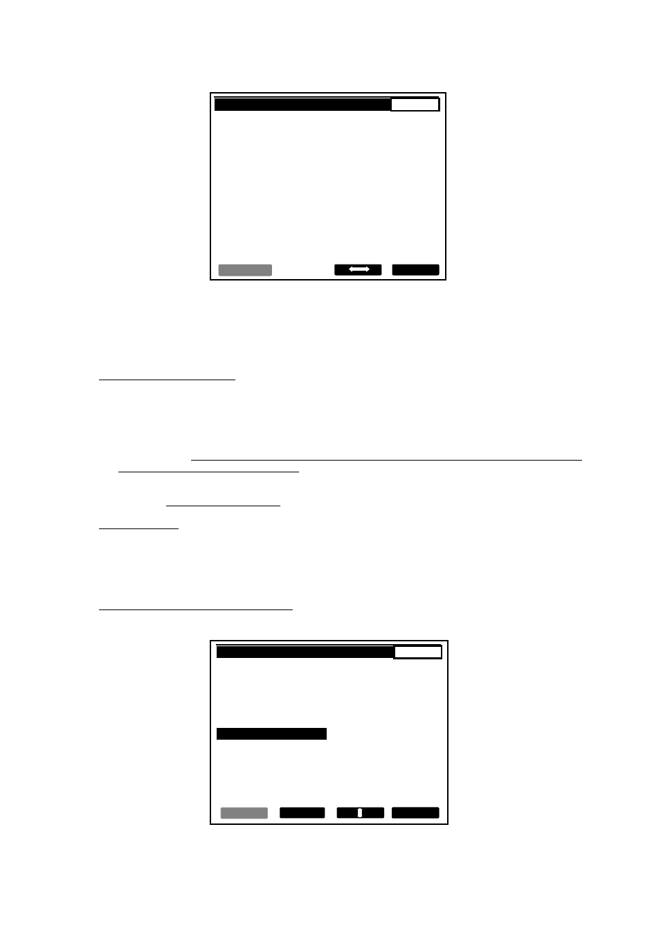
SET UP -> INP. -> CONC. -> RANGE
1 / 0 . 1
MIN.
MAX.
CURRENT VALUE :
6 0
9 0
NEW VALUE :
6 5
9 0
BACK
BACK
BACK
ACCEPT
Fig. 8.7
The procedure is similar with all data source types. The new RANGE data must be within the limits specified
by the default values of the same parameter (see Ch. 6.2).
These RANGE data are used to detect RANGE EXURSIONS documented in the 3 different lists on EVENTS.
Specifying ALARM LIMIT data.
LOW LIMIT and HIGH LIMIT data can be entered one by one (see Fig. 8.6 b)).
NOTES:
1. In the STRIKE ACTIVE state data inputs and data outputs are monitored for RANGE EXCURSIONS. If
detected, the excursions will be logged complete with their names and time stamps in the EVENTS’
HISTORY, and the effected data will be replaced for the calculations by their appropriate range limit
values (RANGE MIN., or RANGE MAX.).
2. In the STRIKE ACTIVE state data inputs and data outputs are monitored for ALARM EXCURSIONS. If
detected, the excursions will be logged complete with their names and time stamps in the EVENTS’
HISTORY without any further action.
Engineering units.
The ENGINEERING UNIT can not be changed: it is automatically selected according to the type of the
selected THIRD INPUT.
The two exceptions are MOTOR CONSUMPTION, in which case A, or kW, and TEMPERATURE, where
Celsius ©, or Fahrenheit (F) can be selected by using CHANGE and ACCEPT or ENTER.
Specifying TRANSMITTER PARAMETERS.
If TRANSMITTER is specified as an input source, further specification is needed (Fig. 8.8).
SET UP -> INPUTS -> LEVEL.
1 / 0 . 1
LEVEL
TRANSMITTER
CLEAR
STANDARD CURRENT
4 - 20 mA
RANGE
0 - 100
LOW LIMIT
5 %
HIGH LIMIT
8 2 %
CHANNEL
NOT SELECTED
ENGINEERING UNIT
%
CHANGE
BACK
ACCEPT
Fig. 8.8