Cut charts -17, Estimated kerf width compensation -17, Cut charts – Hypertherm HD4070 Rev.1 User Manual
Page 142: Estimated kerf width compensation, Metric, English
OPERATION
HyPerformance HD4070
Instruction Manual
4-17
Cut charts
The following cut charts show the consumable parts, cutting speed and the gas and torch settings required for the
specific process.
The HD4070 system will automatically select and adjust the power and gas (including amperage, gas type and gas
flow rate) required for the material and thickness to be cut.
If the Hypertherm Integrated Command THC option is installed, the HD4070 system will also automatically adjust
torch settings required for the specific process, including arc volts, torch standoff, initial pierce height and pierce
time delay.
The numbers shown in the cut charts are the HD4070’s default values and should provide high quality cuts with
minimal dross. Because of differences between installations and material composition, adjustments may be
required to obtain desirable results.
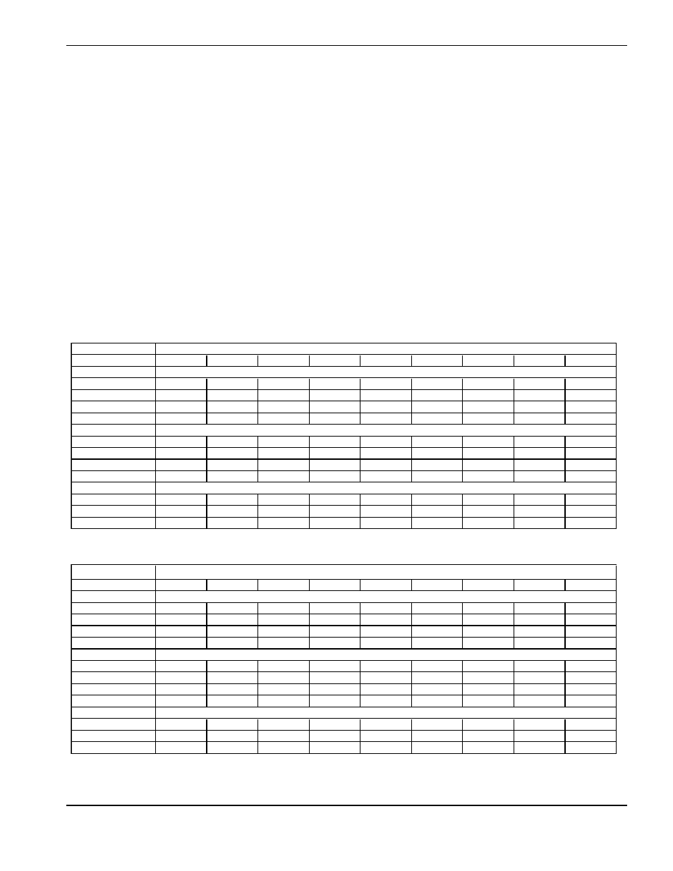
Estimated kerf width compensation
The widths in the chart below are for reference. Differences between installations and material composition may
cause actual results to vary from those shown in the table.
Metric
Process
1.5
3
6
10
12
20
25
32
38
MS
200A O2-N2
2.18
2.26
2.95
130A O2-N2
1.80
2.03
2.11
2.64
3.43
80A O2-N2
1.37
1.73
1.91
30A O2-N2
1.35
1.45
SS
200A H35-N2
3.68
3.81
3.94
130A H35-N2
2.72
2.77
2.90
80A F5-N2
1.19
45A F5-N2
0.58
0.38
0.53
AL
200A H35-N2
2.67
2.92
3.30
130A H35-N2
2.72
2.77
2.90
45A Air-Air
1.07
1.09
1.25
English
Process
0.060"
0.135"
1/4"
3/8"
1/2"
3/4"
1"
1-1/4"
1-1/2"
MS
200A O2-N2
0.086
0.089
0.116
130A O2-N2
0.071
0.080
0.083
0.104
0.135
80A O2-N2
0.054
0.068
0.075
30A O2-N2
0.053
0.057
SS
200A H35-N2
0.145
0.150
0.155
130A H35-N2
0.107
0.109
0.114
80A F5-N2
0.047
45A F5-N2
0.023
0.015
0.021
AL
200A H35-N2
0.105
0.115
0.130
130A H35-N2
0.107
0.109
0.114
45A Air-Air
0.042
0.043
0.049
Thickness (in)
Thickness (mm)