Grip Factory Munich GF-8 User Manual
Page 7
GF-8 Xten Crane System Instruction Manual
Page: 6
4.
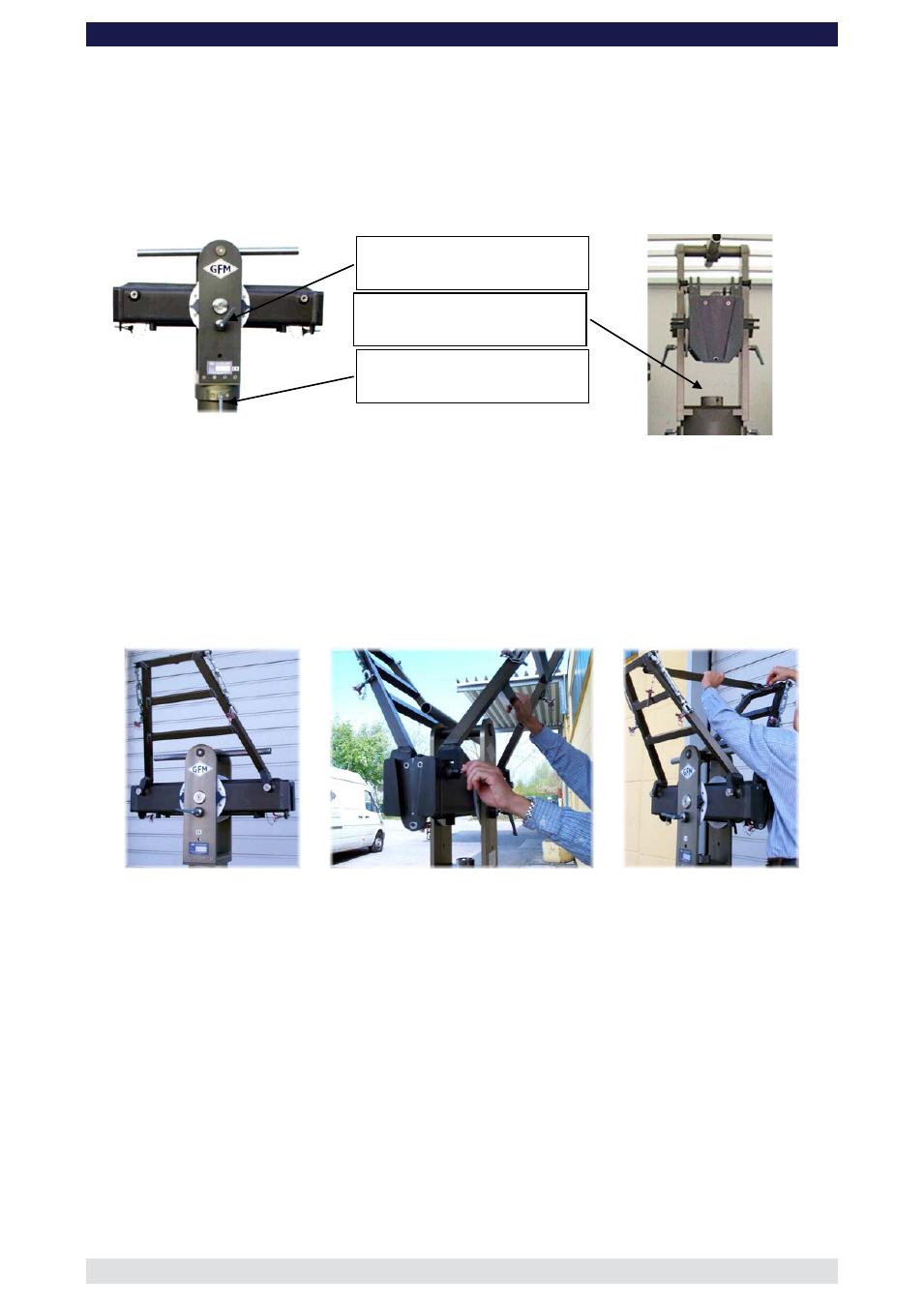
Located on the middle section are 2 tilt friction locks which may be used to lock the tilt
during set-up. Set the pivot arm at 90° to the centre post and lock these friction locks
which can be found on the left and right hand side of the middle section. Mount the
middle section on the mounting column. Lock the locking screw tightly.
Tip:
A 12mm Allen key can be found in the mounting column’s handle to be used
as a lever.
Attention:
Install the middle section to the rotateable bearing of the column with
positive locking. It fits properly only in one position.
Middle section with pan and tilt lock
Tilt brake
Pan brake
Unless otherwise stated it is required to use the rigging system when more than
1 x 150cm / 5ft section is mounted to the front of the crane i.e. all versions except
1 and 9.
5.
Connect the 2 sections of the rigging harness to the middle section of the GF-8.
Ensure that the 4 locking bolts are fastened tightly.
6.
Connect the cross bar to stabilize the rigging harness. Ensure that the 2 locking pins
are inserted fully.
7.
For Standard Versions 1 to 16 connect the 127cm / 4ft rear arm section to the middle
section. For Standard Versions 17 and 18 connect the 150cm / 5ft section to the
middle section. Slip the connection flanges into each other and secure with the
provided safety pin.
Connect the respective 127cm or 150cm parallelogram rod to the middle section,
mount the sliding weight and secure with the locking screw. Other shorter versions
can be built by using the 100cm / 3’ 3” or 150cm / 5’ extension and its parallelogram
rod.
Tip:
To avoid the sections jamming or getting stuck make sure that the sections
are joined parallel. Using a small amount of lubricant also helps. We suggest
rubbing the joints with an oiled rag.
Locking screw