Xten version 1 – Grip Factory Munich GF-8 User Manual
Page 25
GF-8 Xten Crane System Instruction Manual
Page: 24
Assembly & Technical Specifications for the Xten Versions
Attention: The following Xten Versions, 1 to 8 require a 160cm / 5’ 3” section to the
rear i.e. Counterweight Bucket End.
In addition to the standard mounting column, the 30cm / 1ft Column
Extension is also required to achieve a pivot height of 184cm / 6ft.
Note:
A larger rigging harness than the standard and a double rigging rather
than the standard single system is required to the front and rear of the
crane arm.
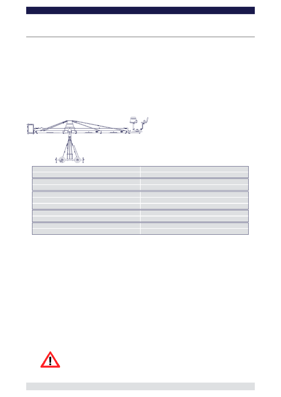
Xten Version 1
(Pivot height 184cm / 6ft, Large Rigging Harness, Rear Extension 160cm / 5’ 3")
Front extension arms required
2 x 150 cm / 5’
Rear extension arm required
1 x 160 cm / 5’ 3”
Lift range
564 cm / 18’ 6”
Maximum Euro-adapter height
483 cm / 15’ 10“
Lift capacity
250 kg / 550 lbs
Counterweight required for max. load
456 kg / 1003 lbs
Counterweight required to balance empty arm
28 kg / 61 lbs
Crane weight (excluding dolly and weights)
203 kg / 446 lbs
Dolly weight
80 kg / 176 lbs
Arm reach (pivot to camera head mount)
401 cm / 13’ 1“
Length of rear end (pivot to outside of bucket)
253 cm / 8’ 3“
Double rigging is required! Observe guidelines on page 423 and additionally ensure
that the Large Rigging Harness is used with double rigging to the rear and front.
Continue from § 9, page 7
10. Connect one of the 150cm / 5’ sections to the middle section. Slip the connection
flanges into each other and secure them with the provided safety pin.
11. Now the lower front rigging system can be assembled. Therefor follow the instructions
as exemplary shown by version 7 and 8 on page 43.
12. After the lower front rigging system was assembled and connected to the connectors
of the first 150cm / 5’ section connect another 150cm / 5’ section to the first one. Slip
the connection flanges into each other and secure them with the provided safety pin.
Note:
After each mounted section the support stand or rostrum can be moved up to
the next fixed section. We recommend to support longer crane versions with
more than one support stand or rostrum.
13. Connect the remaining angle adjuster to the end of the second 150cm / 5’ section and
secure it with the provided safety pin.
Attention: Pinch point