Version 17 – Grip Factory Munich GF-8 User Manual
Page 22
GF-8 Xten Crane System Instruction Manual
Page: 21
Attention: The following versions 17 and 18 require a 150cm / 5ft. section to the
rear i.e. Counterweight Bucket End.
The 30cm / 1ft Column Extension is also required to achieve a pivot
height to 184cm / 6ft. See page 4
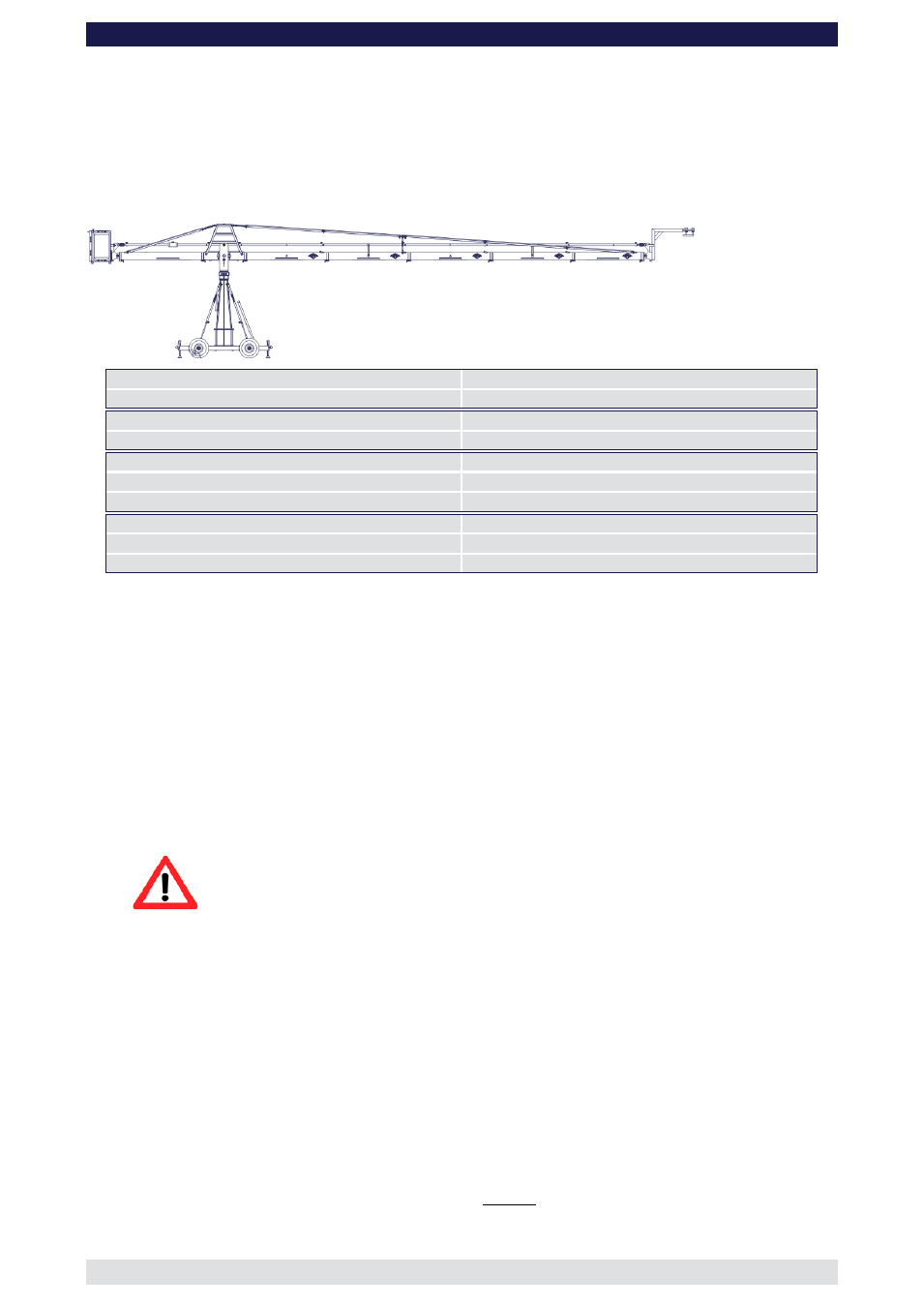
Version 17
(Pivot height 184cm / 6ft, Standard Rigging Harness, Rear Extension 150cm / 5’)
Front extension arms required
4 x 150 cm / 5’ + 127 cm / 4’ 2”
Rear extension arm required
1 x 150 cm / 5’
Lift range
1216 cm / 39’ 10”
Maximum Euro-adapter height
850 cm / 27’ 10“
Lift capacity
50 kg / 110 lbs
Counterweight required for max. load
418 kg / 919 lbs
Counterweight required to balance empty arm
214 kg / 470 lbs
Crane weight (excluding dolly and weights)
239 kg / 525 lbs
Arm reach (pivot to camera head mount)
837 cm / 27’ 5“
Length of rear end (pivot to outside of bucket)
243 cm / 7’ 11“
Rigging is required! Observe guidelines on page 41.
Continue from § 9, page 7
10. Connect one of the 150cm / 5’ sections to the middle section. Slip the connection
flanges into each other and secure them with the provided safety pin.
11. Connect another three 150cm / 5’ sections and the 127cm / 4’ 2” section to the first
150cm / 5’ section. Slip the connection flanges into each other and secure them with
the provided safety pins.
Note:
After each mounted section the support stand or rostrum can be moved up to
the next fixed section. We recommend to support longer crane versions with
more than one support stand or rostrum.
12. Connect the remaining angle adjuster to the end of the 127cm / 4’ 2” section and
secure it with the provided safety pin.
Attention: Pinch point
13. Mount the parallelogram rod support to the respective section as shown on page 40.
14. Connect four 150cm / 5’ parallelogram rods and a 127cm / 4’ 2” rod to the middle
section and in turn to the angle adjuster and secure the connections with the provided
safety pins.
15. Connect the remote bracket to the angle adjuster by inserting the male flange into the
female flange on the angle adjuster. Secure it with the safety pin.
16. Attach the weight bucket to the short end of the crane by inserting the male weight
bucket flange into the female flange on the angle adjuster. Secure it with the 2 safety
pins on the top of the angle adjuster.
Tip:
The angle adjuster has an integrated leveller. By turning it, the vertical plate
on the angle adjuster can be set to a perfect right angle. Correct setting of
the angle adjuster enhances the crane’s balance. Level the weight bucket,
the platform or the remote bracket before loading any weights.